
General information
2. During engine operation, parts of the power plant, and in particular the gas distribution mechanism (timing), are heated to high temperatures, resulting in thermal expansion and a slight increase in the size of the parts. To compensate for thermal deformations, it is necessary to have a certain gap between the camshaft cams and the valve lifters.
3. At small gaps, the valves may not close completely, which will lead to a decrease in the efficiency of the engine, and in some cases to deformation of the valves or burning of their seats.
4. With large gaps, the efficiency of the engine also decreases, increased mechanical noise occurs, and the engine becomes uneven.
5. When adjusting the size of the gaps, it is necessary to take into account the condition of the valves - the seal in the valves is satisfactory, the valves do not have excessive gaps in the guides, and the ends of the valve stems are not broken. If these conditions are not observed, it is not possible to correctly adjust the thermal gaps.
6. Checking and adjusting the valves is carried out as necessary, as a rule, during the next scheduled maintenance, as well as after repair / disassembly of the timing or if there is noise during the operation of the valves.
Note: The valve clearances are checked and adjusted according to «cold» engine - the engine has cooled down to ambient temperature.
7. When performing the clearance check procedure, it is recommended to draw up a plate / diagram with the valve numbering in advance for the convenience of recording the measurement results.
8. Before starting work, check the correct installation of the valve timing (see Section 6) and disconnect the battery (see chapter 5).
Note: After every battery disconnection, the steering wheel angle sensor must be adjusted (with appropriate equipment).
Clearance check
9. To perform a check and adjustment of the valves, it is necessary to remove the nozzles (see chapter 4).
Attention: The fuel system is very sensitive to the ingress of even small particles of contamination - strictly follow all the instructions in the relevant section, otherwise the system may fail and an expensive engine repair will be required!
10. Turn the crankshaft so that the cams of the corresponding pairs (see resist. illustration) were directed upward.
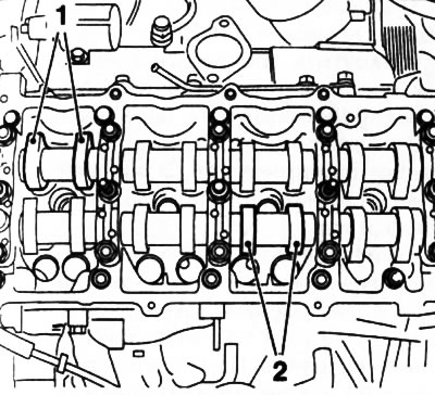
9.10. Rotate the crankshaft until the cams (1) And (2) were directed upward
11. Check the valve clearances of the specified pairs with a set of blade feeler gauges - appropriate feeler gauge (see specs) should enter the gap very tightly with a slight «snacking», otherwise the clearance needs to be adjusted. If the gap value deviates from the standard values, it is necessary to determine the actual gap value - write down the measured value. Adjustment can be made immediately or after checking the clearances of all valves.
12. Then check and adjust the gaps alternately at the second and sixth, third and fifth, first and fourth (see resist. illustration) a pair of cams, each time turning the engine crankshaft half a turn in the direction of rotation (clockwise) - the cams of both adjustable pairs should look up.
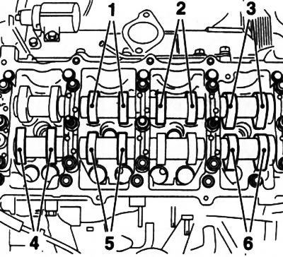
9.12. Numbering of pairs of cams of camshafts
Gap adjustment
13. The backlash in the valve is regulated by replacement of adjusting washers. Turn the crankshaft so that the drive cam of the valve to be adjusted is turned with the heel to the pusher.
Note: Make sure the engine is not at the TDC position of the corresponding valve, as changing the shim will require compressing the valve spring, which can cause the valve to stop against the piston crown.
14. To remove the old washers, turn the pusher so that the pusher groove points outward, then press the pusher using the Opel-KM-6090 special tool (see resist. illustration).
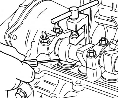
9.14. Replacing shims (Y17DT engines (L) /Z17DTH))
Attention: When using this tool, pay attention to the markings: «1B» - for inlet valves, «EX» - for exhaust valves!
15. If no special tool is available, insert a large flat-bladed screwdriver between the edge of the tappet and the base of the camshaft. Carefully, using a screwdriver as a lever, drown the pusher until it is possible to remove the adjusting washer. To remove the washer, it is most convenient to use a magnet or a magnetized rod (see resist. illustration).
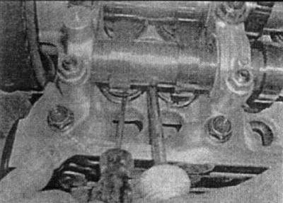
9.15. Removing the shim is best done with a magnetized rod
16. Wipe the washer and measure its thickness with a micrometer.
Note: Washers are marked (see resist. illustration).
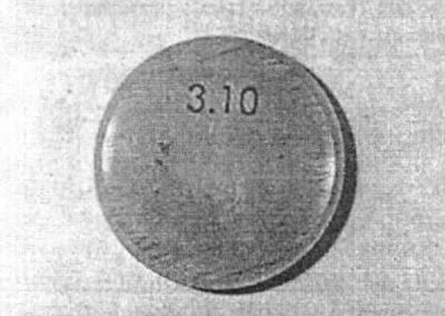
9.16. The thickness of shims is usually stamped on one of their end faces (washers should be installed with markings to the pusher)
17. The calculation of the thickness of the new shim is made according to the formula: N \u003d T + A - S
T = thickness of the removed washer, (for example - 3.15 mm).
A = measured valve clearance (for example - 0.50 mm).
S = valve clearance adjustment value (for example - 0.40 mm).
For this example, the thickness of the new shim is N=3.25 mm.
Note: Adjusting washers can be reused if they do not show obvious signs of wear. It may be possible to make the required adjustment by simply moving the washers from one pusher to another. Record and save for possible future adjustments to the thickness of all washers. If the washer thickness marking is worn out and cannot be read, further use of the washer is not recommended.
18. Prepare a washer of the required thickness, lubricate it with clean engine oil. Squeeze out the pusher and put the washer into it with the marking down.
19. Similarly, adjust the gaps of the remaining valves requiring adjustment, in the sequence indicated in paragraph 12 (see above).
20. Turn the crankshaft several times to seat the washers on the tappets, then check the clearances before installing the camshaft housing cover, repeat the adjustment if necessary.
21. Replace all removed elements. Connect the battery.
Visitor comments