
General information
2. During engine operation, parts of the power plant, and in particular the gas distribution mechanism (timing), are heated to high temperatures, resulting in thermal expansion and a slight increase in the size of the parts. To compensate for thermal deformations, it is necessary to have a certain gap between the camshaft cams and the valve lifters.
3. At small gaps, the valves may not close completely, which will lead to a decrease in the efficiency of the engine, and in some cases to deformation of the valves or burning of their seats.
4. With large gaps, the efficiency of the engine also decreases, increased mechanical noise occurs, and the engine becomes uneven.
5. When adjusting the size of the gaps, it is necessary to take into account the condition of the valves - the seal in the valves is satisfactory, the valves do not have excessive gaps in the guides, and the ends of the valve stems are not broken. If these conditions are not observed, it is not possible to correctly adjust the thermal gaps.
6. Checking and adjusting the valves is carried out as necessary, as a rule, during the next scheduled maintenance, as well as after repair / disassembly of the timing or if there is noise during the operation of the valves.
Note: The valve clearances are checked and adjusted according to «cold» engine - engine cooled to ambient temperature.
7. When performing the clearance check procedure, it is recommended to draw up a plate / diagram with the valve numbering in advance for the convenience of recording the measurement results.
8. Before starting work, disconnect the battery and, if necessary, remove the right front wheel (see Introduction).
Z16XEP engine
Clearance check
9. Remove the air filter (see chapter 4).
10. Remove the ignition module (see Chapter 1, Section 22)
11. Remove the cylinder head cover (see Section 10).
12. Bring the piston of the first cylinder to the TDC position of the end of the compression stroke (see Section 6), while the cams of the inlet valves of the 2nd cylinder and the exhaust valves of the 3rd cylinder (see resist. illustration) should be directed upwards and located symmetrically at a slight angle inward (to the center of the cylinder head).
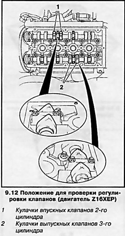
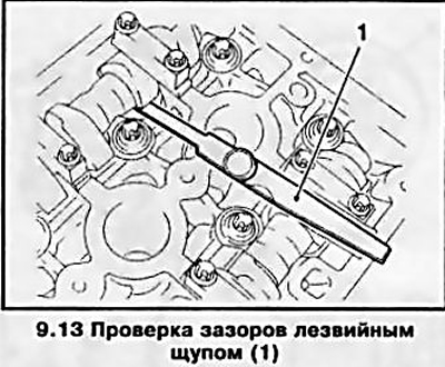
13. On these cams using a blade type feeler (see resist. illustration) check the gaps. If the gap exceeds / does not reach the standard value (see specs), determine the actual gap using a set of feeler gauges and record the value.
14. Turn the crankshaft half a turn in the direction of engine rotation - this corresponds to ¼ turn of the camshaft gears (follow the marks on the wheels). In this position, check the clearance on the cams of the intake valves of the 1st cylinder and the exhaust valves of the 4th cylinder. If the measurement result deviates from the standard, also write it down.
15. Turn the crankshaft another half turn - check the gap on the cams of the inlet valves of the 3rd cylinder and the exhaust valves of the 2nd cylinder.
16. Turn the crankshaft another half turn - check the valve clearance on the cams of the intake valves of the 4th cylinder and the exhaust valves of the 1st cylinder.
Gap adjustment
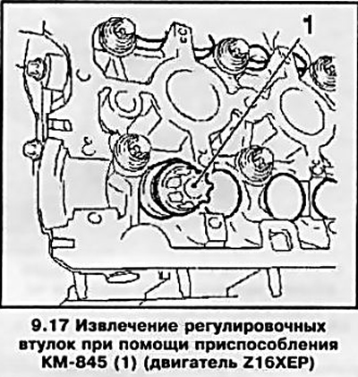
17. On this engine, the valve clearances are adjusted with the camshafts removed. After removing the camshafts (see Section 10) remove using the KM-845 tool (see resist. illustration) valve adjusters.
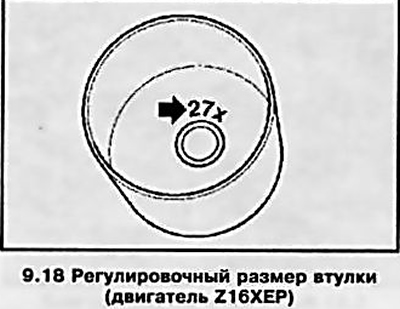
18. On the inside of the bushings (see resist. illustration) an adjusting size is applied, which corresponds to bushings with a certain thickness - for example, size 20 corresponds to bushings with a thickness of 3.20 mm.
Note: A table of adjustment dimensions must be supplied with the bushings.
19. The calculation of the thickness of the new adjusting sleeve is made according to the formula: N \u003d T + A - S
T = thickness of the removed sleeve, (e.g. 3.20 mm, setting size 20)
A = measured valve clearance (for example, for the intake valve - 0.31 mm)
S = valve clearance adjustment value (for example, for the inlet valve - 0.25 mm)
For this example, the thickness of the new shim N should be 3.26 mm. The adjustment dimension closest to this value is 27 - 3.265 mm.
Note: Write down and save for possible future adjustments the dimensions of all bushings installed.
20. Upon completion of the adjustment, reinstall all the removed elements. The procedure for installing the cylinder head cover is described in detail in Section 10.
Z19DT engine
Clearance check
21. Raise the car on a lift and remove the engine crankcase protection (see Section 5).
22. Lower the car and remove the engine cover (see section 2).
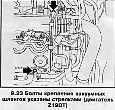
23. Disconnect 2 vacuum hoses, for which unscrew the fixing bolts (see resist. illustration).
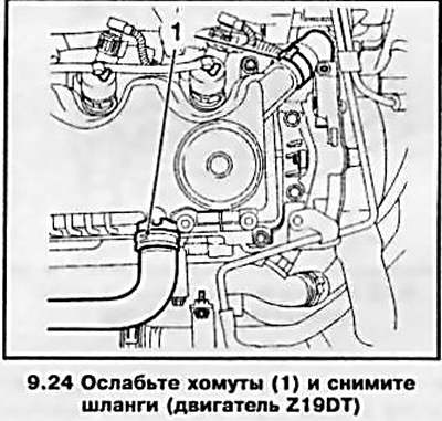
24. Disconnect the 2 hoses by first loosening and fully sliding back the clamps (see resist. illustration).
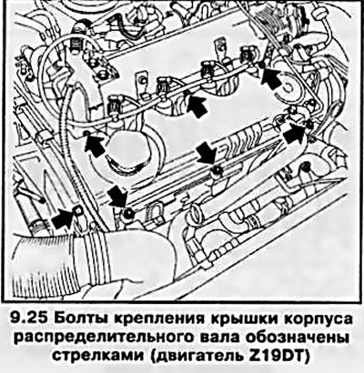
25. Turn away bolts of fastening and remove a cover of the case of a camshaft (see resist. illustration).
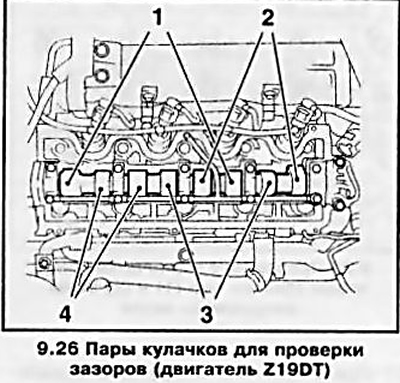
26. Turn a cranked shaft so. to the cams of the first pair (see resist. illustration) were directed upward.
Note: Methods for turning the crankshaft are given in Section 6.
27. Check the gaps of the indicated cams with a set of blade feeler gauges - appropriate feeler gauge (see specs) should enter the gap very tightly with a slight «snacking», otherwise the clearance needs to be adjusted. If the gap value deviates from the standard values, it is necessary to determine the actual gap value - write down the measured value.
28. Turn the crankshaft half a turn in the direction of engine rotation and check the valve clearances at the second (see illustration 9.26) pairs of cams (cams should be pointing up). If the gap value deviates from the reference value, record the result of actual measurements. Then turn the crankshaft another half turn and check the valve clearance at the third and fourth (see ibid) pair of cams.
Gap adjustment
29. Turn the crankshaft so that the drive cam of the valve to be adjusted is turned with its heel to the pusher.
Note: Make sure the engine is not at the TDC position of the corresponding valve, as changing the shim will require compressing the valve spring, which can cause the valve to stop against the piston crown.
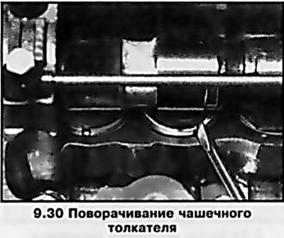
30. Rotate the cup pusher with the groove out (see resist. illustration).
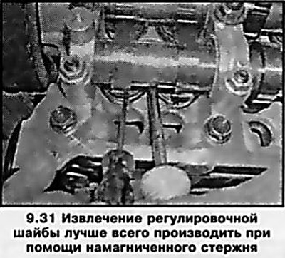
31. If there is no special tool Opel-EN-46797 and EN-46799 at hand, insert a large flat-blade screwdriver between the edge of the pusher and the base of the camshaft. Carefully, using a screwdriver as a lever, drown the pusher until it is possible to remove the adjusting washer. Removing the washer is easiest to do with a magnetized rod (see resist. illustration).
32. Wipe the washer and measure its thickness with a micrometer.
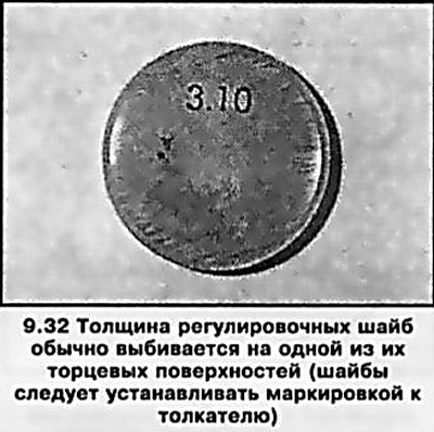
Note: Washers are marked (see resist. illustration), which, however, may be lost as a result of wear.
33. The calculation of the thickness of the new shim is made according to the formula: N \u003d T + A - S
T = thickness of the removed washer, (for example - 3.15 mm)
A = measured valve clearance (for example - 0.45 mm)
S = valve clearance adjustment value (for example - 0.35 mm)
For this example, the thickness of the new shim is N= 3.25 mm.
Note: It may be possible to make the required adjustment by simply moving the washers from one pusher to another. Record and save for possible future adjustments to the thickness of all washers.
34. Prepare a washer of the required thickness, lubricate it with clean engine oil. Squeeze out the pusher and put the washer into it with the marking down.
35. In a similar manner, adjust the gaps of the remaining valves that need adjustment.
36. Turn the crankshaft several times to seat the washers on the tappets, then check the clearances before installing the camshaft housing cover. Clean the sealing surfaces and install the cover on a new gasket. Tighten 7 bolts to 10 Nm.
37. Replace all removed elements. Install the crankcase guard and wheel, then lower the vehicle to the ground and tighten the wheel bolts to the correct torque. Connect the battery.
Z17DT engines (L/H)
Clearance check
38. To check and adjust the valves, it is necessary to remove the nozzles (see chapter 4).
Attention: The fuel system is very sensitive to the ingress of even small particles of contamination - strictly follow all the instructions in the relevant section, otherwise the system may fail and an expensive engine repair will be required!
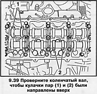
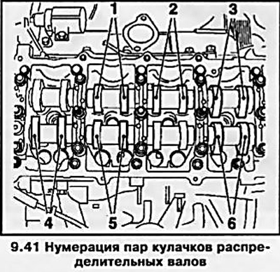
39. Turn the crankshaft so that the cams of the corresponding pairs (see resist. illustration) were directed upward.
40. Check the valve clearances of the indicated pairs with a set of blade feeler gauges - appropriate feeler gauge (see specs) should enter the gap very tightly with a slight «snacking», otherwise the clearance needs to be adjusted. If the gap value deviates from the standard values, it is necessary to determine the actual gap value - write down the measured value. Adjustment can be made immediately or after checking the clearances of all valves.
41. Then check and adjust the gaps alternately at the second and sixth, third and fifth, first and fourth (see resist. illustration) a pair of cams, each time turning the engine crankshaft half a turn in the direction of rotation (clockwise) - the cams of both adjustable pairs should look up.
Gap adjustment
42. The clearance in the valve is adjusted by replacing the shims. To remove the old washers, turn the pusher cup so that the pusher groove points outward, then press the pusher cups with the special tool Opel-KM-6090 (see resist. illustration).
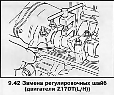
Attention: When using this tool, pay attention to the markings: «IB» for intake valves «EX» — for exhaust valves!
43. To calculate the thickness of a new shim, see paragraph 33. Lubricate the shim with clean engine oil before installing it.
44. At the end of the adjustment, turn the crankshaft several times to shrink the washers on the pushers and check the gaps on all valves again. Reinstall all removed components.
Visitor comments