
2. If necessary, it is recommended to replace the male and female rotors together. Operations for checking the condition and adjusting the oil pump should be entrusted to service station specialists.
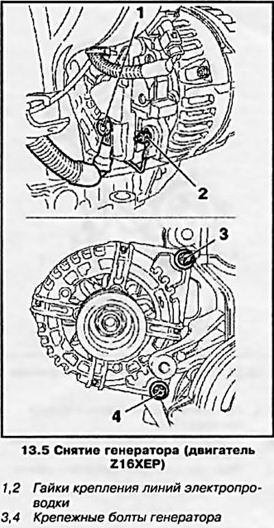
Z16XEP engine
3. Disconnect the wire from the negative battery terminal.
4. Remove the multirib belt (see Section 7) and oil pan (see Section 12).
5. Remove the generator, for which disconnect the electrical wiring, unscrew the 2. fixing bolts (see resist. illustration) and move the generator back (see also chapter 5).
6. Remove the right engine mount (see Section 5) and brackets for its attachment to the engine block. Remove toothed belt (see Section 8), remove the toothed belt tensioner and guide pulley.
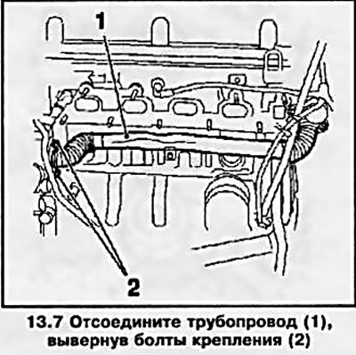
7. Having unscrewed 2 bolts, disconnect the pipeline of the cooling system (see resist. illustration).
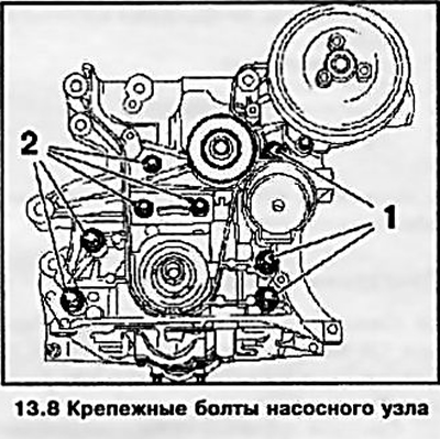
8. Turn out 8 fixing bolts (see resist. illustration) and remove the pump assembly. Mounting bolts have different lengths - remember the order in which they are installed or mark the bolts.
9. Using a suitable tool, carefully remove the crankshaft front oil seal.
10. Replace the seal before installing the pump assembly. Tighten the oil pump mounting bolts to the specified torque. Lubricate the surfaces of the new crankshaft oil seal with silicone grease (white color), install protective sleeve (see resist. illustration 13.10a) on the neck of the crankshaft and fill the oil seal into the mounting socket along it. Using the KM-6351 fixture. (see resist. illustration 13.10b) press in the seal.
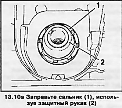
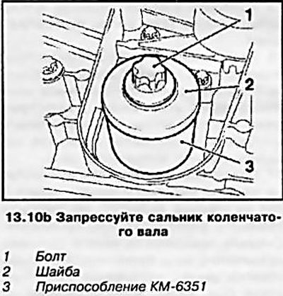
11. Installation of other removed components is made in an order, the return to an order of their removal.
Z18XE engine
12. Remove the oil pan (see Section 12), engine cover (see section 2) and toothed belt (see Section 8).
13. Remove tensioner and toothed belt guide roller.
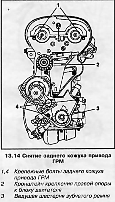
14. Remove gears (see Section 5) and the drive gear of the toothed belt, unscrew the fixing bolts and remove the rear timing cover (see resist. illustration).
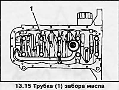
15. Having unscrewed 3 bolts, remove the oil intake pipe (see resist. illustration).
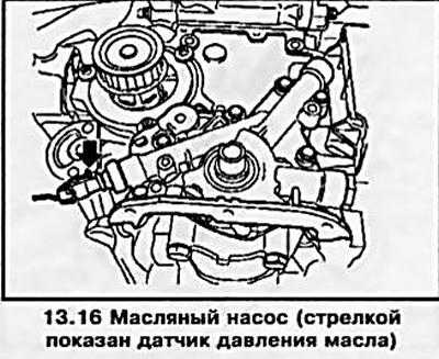
16. Disconnect the oil pressure sensor wiring connector, remove the 7 mounting bolts and remove the oil pump (see resist. illustration). Using a suitable tool, carefully remove the crankshaft front oil seal.
17. When installing, make sure that the protrusion on the oil pump housing fits into the groove on the water pump housing, do not forget to replace the gasket. Lubricate the surfaces of the new crankshaft oil seal with silicone grease (white color), install protective sleeve (see resist. illustration) on the neck of the crankshaft and fill the oil seal into the mounting socket along it. Press the oil seal using the KM-6010 tool.
13.17 Installing the oil pump (Z1SXE engine)
1 Oil pump sealing gasket
2 Protective sleeve
3 Bolt
4 Adaptation KM-6010
5 Washer
18. Installation of other removed components is made in an order, the return to an order of their removal.
Z20LE engines (L/R/H)
19. Remove the oil pan (see Section 12), ignition module (see Chapter 1, Section 22) and toothed belt (see Section 8).
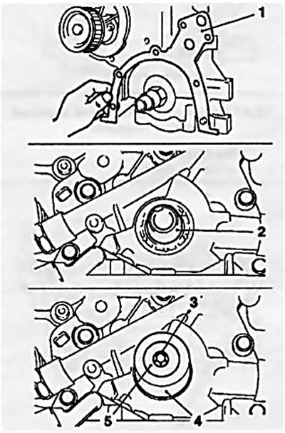
20. Remove the camshaft gears (see Section 5) and drive gear of the timing drive, tension and guide rollers, mounting bracket for the right engine mount (see resist. illustration). Remove the mounting bolts and remove the rear timing cover.
13.20 Removing the rear timing case (Z20LE engines (L/R/H))
1 Camshaft sensor
2 guide rollers
3 Right engine mount bracket
4 Tension roller
5 Adaptation KM-662-S
6 Timing gear
7.8 Mounting bolts
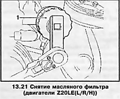
21. Disconnect the wiring connector from the oil pressure sensor and using the KM-726-A tool (see resist. illustration) remove the oil filter (see also Chapter 1).
22. Turn out bolts of fastening of oil lines from the case of an oil cooler, turn out by means of adaptation KM-943. threaded connection for filter installation, remove the cooler housing from the oil pump (see resist. illustration).
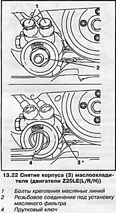
23. Remove friction washer (if necessary, heat it with a jet of hot air), unscrew the fixing bolts of the oil pump housing and remove the pump (see resist. illustration). Remove the packing gland from the pump housing.
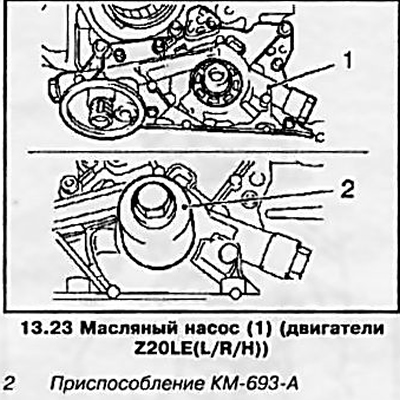
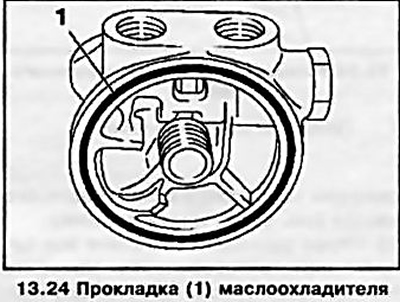
24. Installation of all removed components is made in an order, the return to an order of their removal. Don't forget to replace the oil pump seal. After installing the oil pump housing, lubricate the surfaces of the new oil seal with a generous layer of silicone grease (white color), and fill the stuffing box into the oil pump mounting socket using the KM-693-A tool (see illustration 13.23). Before installing the oil cooler housing, replace its sealing gasket (see resist. illustration).
Z14XEP engine
25. Remove the timing chain and crankshaft front oil seal (see Section 8).
26. Remove the oil pump cover (see resist. illustration) and remove the driven and driving rotor of the oil pump.
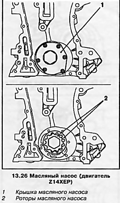
27. Installation is made in the reverse order of removal.
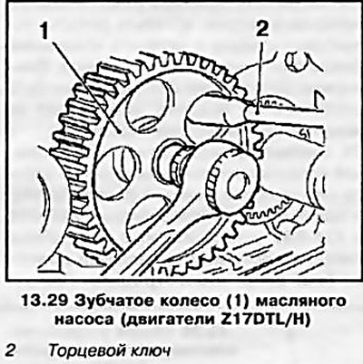
Z17DTL/H engines
28. Remove the oil pan (see Section 12) and toothed timing belt (see Section 8).
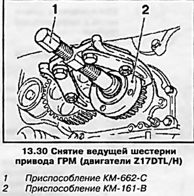
29. Remove the oil pump gear, holding it from turning with a socket wrench (see resist. illustration).
30. With the help of special devices (see resist. illustration) Remove the timing drive gear.
31. Turn out 9 fixing bolts and uncover the oil pump.
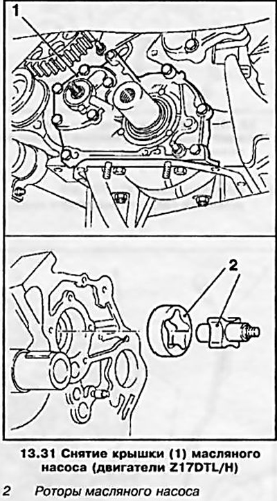
Attention: The bolts have different lengths - remember the order in which they are placed! Then remove the oil pump rotors (see resist. illustration).
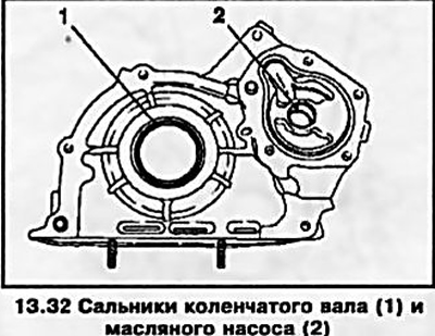
32. Using a suitable tool, carefully so as not to damage the seating surfaces, remove the crankshaft and oil pump oil seals (see resist. illustration).
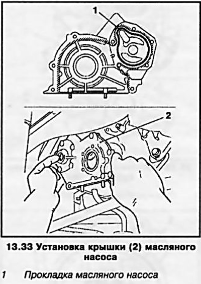
33. Clean all mating surfaces before installation. Apply sealant (black color) on the oil pump cover, replace the pump seal, insert the rotors, install the cover and tighten the fixing bolts (see resist. illustration).
Attention: The tightening of the bolts must be completed no later than 10 minutes after applying the sealant!
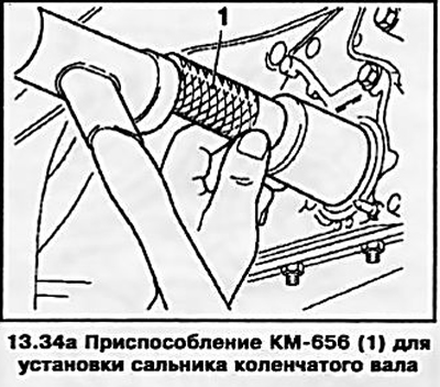
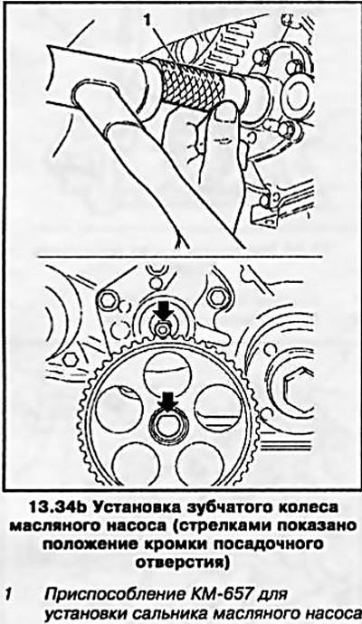
34. Lubricate the surfaces of the new crankshaft and oil pump seals with silicone grease (white color) and with the help of KM-656 devices. and KM-657. install them in the seats - tap the seals all the way (see resist. illustrations). When installing the gear wheel, pay attention to the position of the edge of the mounting hole.
35. Installing the remaining removed components is carried out in the reverse order of their removal.
Z13DT engine
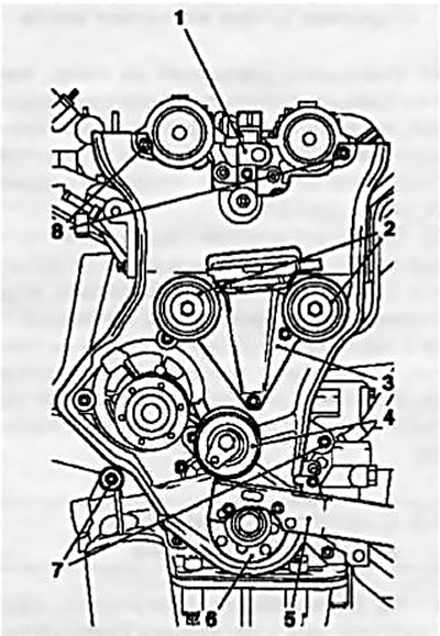
36. The lubrication system of this engine is fundamentally similar to the lubrication system of the Z14XEP engine (see resist. illustration).
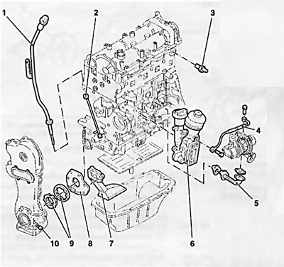
13.36 General arrangement of the Z13DT engine lubrication system
1 Oil dipstick with guide tube
2 Oil line
3 Oil pressure sensor
4 Turbocharger oil supply line
5 Turbocharger oil return line
6 Oil filter housing with oil cooler and oil filler neck
7 Oil intake pipe
8 Oil pump cover
9 Oil pump rotors
10 Safety valve
Visitor comments