
Examination
1. The engine is rigidly connected to the transmission assembly and has a common suspension with it, which is made in the form of a subframe and 4 supports - the right and left supports are attached to the side members, and the front and rear supports are attached to the subframe. The general layout of the suspension supports of the power unit is shown in resist. illustrations.
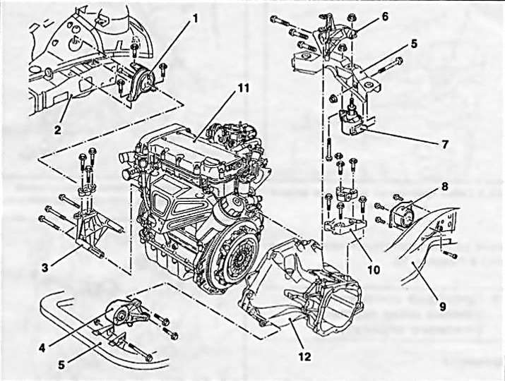
18.1 The general layout of the suspension mounts of the power unit on the Opel Astra / Zafira models
1 Right leg
2 frame
3 Bracket right support
4 Front support
5 subframe beam
6 Rear support bracket
7 Torsional load absorber
8 Left leg
9 Subframe
10 Transmission support
11 Engine
12 Transmission
2. If necessary, in order to ensure freedom of access, jack up the front of the car and place it on props. If equipped, remove the crankcase protection.
3. Check up a condition of rubber pillows of support. In case of detection of cracks, delaminations, separation from the metal substrate, signs of rubber hardening, etc. defects, replace the support.
4. Using a torque wrench, check the tightening forces of the fasteners of the supports.
5. While levering the mount, check the supports for signs of excessive play - if necessary, ask an assistant to rock the unit in different directions and observe the behavior of the supports. The backlash present in new components leads to rapid wear of the bearings. Replace defective components.
Replacement
Note: Before removing components, mark their installation positions with paint.
Right support
6. To remove the right support, you must install special tools (see Section 5) and unscrew the bolts securing the support to the side member and to the engine bracket (see illustrations 7.19, 6.22).
front support
7. Apply the parking brake, then jack up the front of the vehicle and place it on jack stands.
8. To unload the support, support the engine with a trolley jack, - in order to distribute the load, lay a wooden block between the head of the jack and the oil pan.
Attention: When jacking up the power unit, be careful - do not load the exhaust system, if necessary, disconnect the front pipe from the exhaust manifold (see chapter 4).
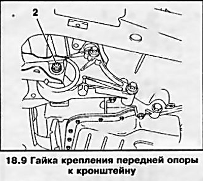
9. Give a nut of fastening of a support to an arm and remove it together with a washer. Remove fixing bolt (see resist. illustration).
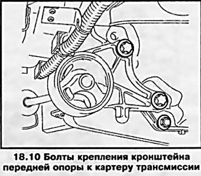
10. Turn out bolts of fastening of an arm of a support to a case of transmission (see resist. illustration) and remove it complete with cushion.
11. Check the condition of all support components. Replace worn and damaged parts.
12. Installation is made in an order, the return to removal, tighten fixing bolts and a nut with demanded effort. Lower the car to the ground.
Rear support
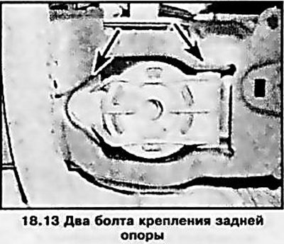
13. Mounting of the rear support is shown in Ref. illustrations. The procedure for replacing it is the same as for the front support (see above).
Left support
14. Set the parking brake, jack up the front of the car, place it on jack stands and remove the crankcase protection.
15. Remove the battery, unscrew the mounting bolts and remove the battery support tray (see chapter 5).
16. Install the support remover (see Section 5) or support the transmission with a trolley jack by placing a block of wood between the jack head and the pallet to distribute the load.
17. Turn out fixing bolts and remove a basic arm of fastenings from transmission (see resist. illustration).
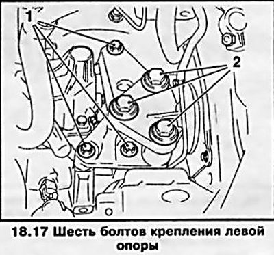
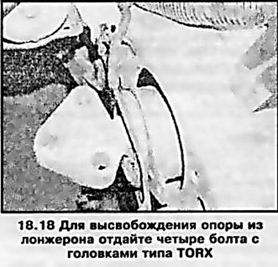
18. Turn out four fixing bolts with heads like TORX and remove a support, separating it from a body (see resist. illustration).
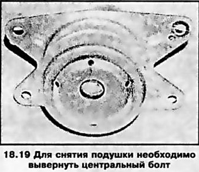
19. If necessary, the support can be disassembled, for which it is necessary to unscrew a single bolt threaded through the center of the pillow (see resist. illustration).
20. Installation is carried out in the reverse order. Make sure all fasteners are tightened to the correct torque.
Visitor comments