
2. It should be noted right away that this procedure is quite complicated for an ordinary motorist and requires the use of fairly serious lifting and rigging and some other equipment. It is essential to have an appropriate work area with enough space to accommodate the vehicle, a sturdy workbench/mounting stand, and the necessary materials, equipment, and components to be removed from the engine. The best option is a large garage or indoor workshop, equipped with shelving with wide shelves. In extreme cases, just a flat area with an asphalt or concrete surface is suitable.
3. In the process of removing the unit from the car, there are many situations when the help of an assistant is required - agree in advance with one of your comrades or neighbors in the garage. If the engine is removed for the first time by an amateur mechanic, be sure to enlist the support of a specialist or someone who has already performed this procedure on the same vehicle. Some operations can only be performed in a service station (e.g. removal of refrigerant from the A/C system), therefore, part of the procedures that require highly qualified personnel and the use of special equipment will have to be entrusted to car service specialists.
4. Try to plan in advance the entire sequence of actions. Prepare the necessary tools and equipment. It is advisable to wash the engine and transmission. Prepare a set of wrenches and interchangeable sockets with a suitable (preferably ratchet) drive, a couple of sturdy wooden blocks, and enough rags and thinner to remove traces of fuel, oil, and coolant.
5. Due to the peculiarities of the layout and suspension of the engine, it is removed together with the gearbox on a subframe. The power unit is removed by lowering it down from the engine compartment, so equipment will be required to raise the car to a sufficiently high height and securely fix it in the raised position. When performing work on unfastening the engine mount, it must be held from above with a winch (hoist), or from below using a hydraulic jack and a special device for holding the unit on the jack.
Note: The jack must be able to lift the machine by at least 100 cm (1m).
Attention: Make sure that the hoist and rigging correspond in terms of their lifting characteristics to the total mass of the power unit (engine with transmission). Do not forget about the need to strictly comply with safety regulations! Do the work slowly, in an organized manner!
6. First of all, you need to discharge the air conditioning system (with appropriate equipment) - contact the service station of the Opel campaign.
Attention: The path of the A/C system is constantly under pressure!
7. Remove the crankcase / right engine boot (depending on the model) (see Section 5). Remove the front wheels of the car (see chapter «Introduction»).
8. Drain coolant (see chapter 3) and release the pressure in the fuel system through the service fitting using a special tool KM-J-34730-91. (see illustration 11.49) (more see chapter 4).
Attention: Do not forget that fuel is a highly flammable liquid! When working with the components of the power system, observe all fire safety measures taken! Do not smoke, do not approach the place of work with an open flame or an unprotected carrier! Fuel, like most other technical fluids, is one of the carcinogenic and toxic substances. Try to prevent fuel from getting into open areas of the body - use protective rubber gloves and goggles, in case of accidental unexpected contact, thoroughly wash your hands with warm water and soap. Clean up spilled fuel immediately and do not store fuel-soaked rags near open flames. Keep a class B fire extinguisher handy at all times!
9. If the engine is removed for later disassembly or transport, remove the oil filter and drain the oil (see Chapter 1, Section 6). It is advisable to drain the oil from the gearbox.
10. You should also drain the headlight washer fluid.
11. Below is a list of the main operations for preparing the engine for removal, most of them are described in the relevant chapters of the Manual.
Note: Depending on the layout of attachments on the engine and in the engine compartment, the number and procedure for removing attachments may vary.
- a) Remove the air cleaner assembly with air ducts (see Section 4), disconnect all air ducts of the turbocharger;
- b) Disconnect and remove the battery and battery support tray;
- c) Remove partially or completely the exhaust system (see chapter 4) and hoses of the crankcase ventilation system;
- d) Disconnect the fuel lines (see chapter 4);
- e) Disconnect the brake booster servo vacuum hose;
- f) Disconnect the hose from the vacuum pump and the EGR valve - take the hose to the side;
- g) Disconnect and move aside the throttle cables and (with appropriate equipment) tempostat cable - try to remember the routes for laying cables;
- h) Loosen the clamps and remove the upper and lower coolant hoses from the radiator. Disconnect all hoses of the cooling path from the engine, remove the expansion tank;
- i) Remove the front bumper (see chapter 11);
- j) After inserting suitable bolts or rods into the holes of the support brackets, fix the radiator in place;
- k) Take off the headlights (see chapter 12);
- l) On the rear partition of the engine compartment, disconnect the hoses of the cooling path from the heater heat exchanger: squeezing the clamp, move the ring forward and remove the hose from the quick coupling;
- m) On models equipped with an air conditioning system, disconnect from the engine and take aside the lines of the refrigeration path, and if necessary, disconnect the wiring, give the fasteners, remove and tie the A/C capacitor to the front panel (see chapter 3);
- n) Disconnect the electrical wiring;
- o) Release the wiring harnesses from all intermediate clamps and place them on top of the engine, if necessary, remove the fuse box;
- R) Disconnect the shift rods/selector cable from the transmission (see chapter 6 or 7).
- q) Disconnect the clutch release hydraulic hose (RKPP) (see chapter 6);
- r) On models with AT, disconnect the electrical wiring and hoses of the ATF cooling path from the transmission;
- s) Disconnect the intermediate shaft of the steering column, disconnect the steering rods from the steering knuckles;
- t) Remove both drive shafts (see chapter 8).
12. Install the right/left support remover (see Section 5). Remove the right and left engine mounts (see Section 17).
13. Once again make sure that all communication lines are disconnected and nothing prevents the removal of the power unit from the engine compartment.
Attention: Never open the refrigeration path of the A/C system (with appropriate equipment)!
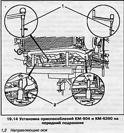
14. Place a trolley jack under the engine. Lift and install the KM-904 and KM-6390 devices on the front subframe (see resist. illustration) - the devices must enter the guide axles into the corresponding holes of the subframe and firmly, without play, fix on the subframe.
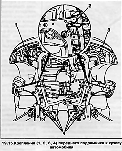
15. Having unscrewed 10 mounting bolts, disconnect the front subframe from the car body (see resist. illustration) (see chapter 10).
16. Lower the power unit on the front subframe, being careful not to pinch the hoses or wiring or damage the radiator/fan. Seek help from an assistant if necessary.
17. Roll out the jack with the power unit attached to it from under the car. Hang the power unit and remove the subframe by disconnecting the front and rear supports. Turn out bolts of fastening of a dome of coupling and separate a transmission from the engine.
18. Installation of all units and removed components is carried out in the reverse order of removal.
Visitor comments