
2. Bring the front wheels of the car into a straight line, remove the key from the ignition and lock the steering wheel.
3. In the driver's footwell, remove the bolt that secures the bottom of the intermediate steering column shaft to the steering gear input shaft. Separate the intermediate shaft and take it to the side.
4. Remove the battery from the tray (see chapter 5).
5. Remove and set aside the expansion tank, having previously disconnected the electrical wiring from it.
Note: The coolant does not need to be drained, but be careful not to accidentally disconnect any coolant hose.
6. On petrol models disconnect 2 sockets of an electrical wiring of a lambda probes.
7. Remove the headlights (see chapter 12).
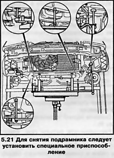
8. Fix the radiator on the front panel by threading 2 bolts into the side mounts - the lower, rubber radiator mounts are installed on the subframe.
9. Remove the cover from the fuse box on the left side of the engine compartment and disconnect the power steering fuse wiring.
10. Disconnect the steering harness connector, loosen the mounting nut and disconnect the steering harness ground cable from the body panel - try to remember the wiring diagram, then lower the latter down onto the steering gear housing.
11. If equipped, remove the engine cover (see chapter 2) and remove the intake duct (see chapter 4).
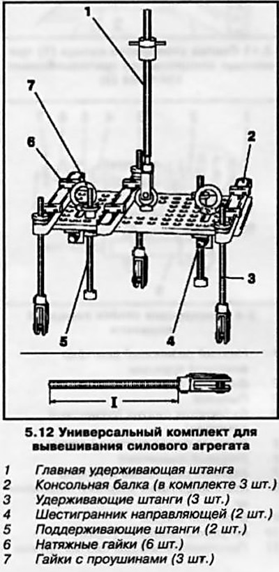
12. Hang the power unit from above. To hang the power unit at branded stations, use a special universal kit (see resist. illustration), depending on the engine model, the rigging equipment is mounted in the appropriate order. This kit allows you to hang the unit on a special cross beam, which is installed on the front side members of the car above the engine compartment. It also allows, within certain limits, sufficient for repair work, to raise and lower the power unit.
13. Raise the vehicle on a lift and place it on jack stands. Remove both front wheels. If equipped, remove the crankcase protection and steering gear heat shield.
14. Remove elements of protection of an arch of the right forward wheel.
15. Disconnect on both sides of the stabilizer bar from the suspension struts.
16. Disconnect the tie rod ends from the steering knuckles (see Section 12).
17. Turn out bolts of coupling collars of rotary fists and release from them fingers of spherical support.
18. Remove the downpipe, catalytic converter and the middle section of the exhaust system (see chapter 4).
19. Release the gear shift rods from the holders on the gearbox (see chapter 6 and 7)
20. Separate the rear support of the power unit from the transmission, then disconnect the front support from the subframe (see chapter 2).
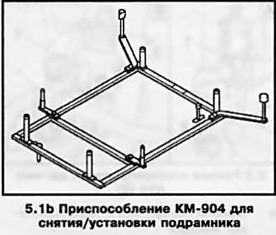
21. Support the subframe with a trolley jack, - in order to distribute the load, place a special device on the head of the jack (see resist. illustration), in its absence, suitable wooden bars can be placed.
22. Clearly mark the position of the subframe and its mounting bolts relative to the car body - specialists use special conductors during installation.
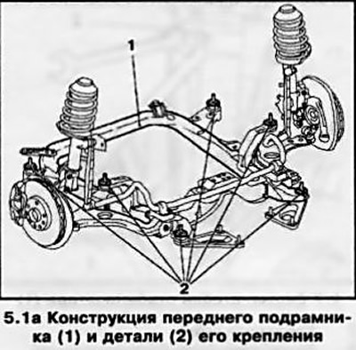
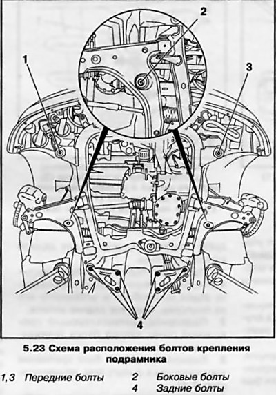
23. Turn out bolts of fastening of a stretcher. The bolts come in different lengths - try to remember the location of each one. The general layout of the fasteners is as follows: 2 bolts in front, 2 bolts above the suspension arms and 6 bolts on triangular brackets (see resist. illustration).
Attention: Never use impulse or impact electric drills to remove the bolts!
24. With the help of an assistant, lower the subframe - try not to damage the steering wiring.
25. If necessary, remove and replace the elements installed on the subframe.
26. Installation is carried out in the reverse order to the dismantling of the components. Follow. for the correct alignment of the landing marks applied during the dismantling process, tighten all fasteners with the required force.
Visitor comments