
Note: Station wagon and Zafira suspensions are similar in design to those used on Hatchback models. The difference between the models lies in the wheelbase, which is 75 mm longer for the Station Wagon models and 89 mm longer for the Zafira models than the Hatchback models.
Attention: When assembling the elements of the suspension and steering structure, it is imperative to comply with the requirements for the tightening force of threaded connections (see specs)! In the absence of the necessary experience, repair work should be carried out at the service station.
1. The design of an independent front suspension with a subframe and lower control arms, MacPherson struts and an anti-roll bar is shown in Res. illustrations. The bearing element of the front suspension is a closed subframe, which is attached to the body at 6 points through shock-absorbing bushings. Additionally, 2 side supports are connected to the bottom of the body at the rear. The struts consist of telescopic shock absorbers and coil springs and are attached with their upper ends to reinforced supports on the mudguards of the front fenders, and with their lower ends to the steering knuckle assemblies. The hub with the wheel bearing is made in the form of a single compact unit, the non-adjustable bearings do not require maintenance. The hub assembly is installed in the steering knuckle. The lower parts of the steering knuckles are connected to the lower suspension arms by means of ball bearings. The inner ends of the levers are attached to the subframe by means of rubber-metal salenbloks, limiting the lateral and longitudinal movement of the front wheels. An anti-roll bar is standard on all models. The stabilizer is mounted on a subframe and connected to the suspension struts by means of two struts, which, depending on the model, can be plastic or steel. It is designed to compensate for the lateral roll of the car when cornering. The front suspension does not require maintenance during operation.
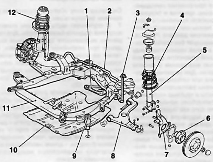
1.1 Front suspension design
1 Triangular reinforcement rear subframe holder
2 Stabilizer barbell transverse stability
3 The stabilizer bar of the transverse stability
4 Helical spring shock absorber
5 Shock absorber
6 Hub assembly
7 Steering knuckle
8 Suspension control arm
9 Rubber-metal support
10 Crankcase protection
11 Subframe
12 shock absorber
2. Rear torsion bar suspension consists of 2 trailing arms welded to a U-shaped cross beam (see resist. illustration). The rear ends of the suspension arms are equipped with saddles and sockets for mounting spring assemblies and shock absorbers, as well as vertical flanges to which rear wheel hub assemblies are bolted together with brake shields. At the front ends of the levers are equipped with salenbloki. Bolts are threaded through the salenbloks, fixing the suspension arms in brackets bolted to the side members of the body. The upper ends of the shock absorbers are attached to the load-bearing elements of the bottom of the body. The springs are installed separately from the shock absorbers (which increases the space of the cargo compartment) and are fixed with two saddles, one of which is attached to the flange on the lever, the other to the bottom of the car. Wheel bearings are built into non-separable hub assemblies. Station wagon models can be equipped with a rear ride height adjustment system (see chapter «Controls and methods of operation»).
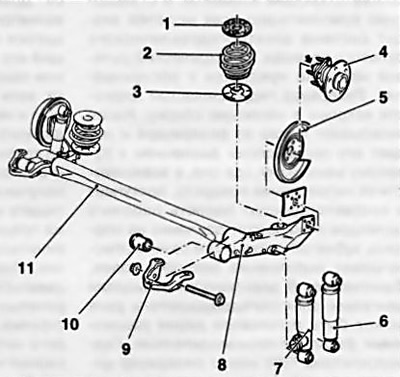
1.2 Rear suspension design
1 Upper seat of the helical spring
2 Coil spring
3 Lower seat of the helical spring
4 Hub assembly
5 Brake shield
6 Telescopic damper (models without rear height adjustment)
7 Telescopic damper (models with CDC rear height adjustment)
8 Trailing arm
9 Suspension arm mounting bracket
10 Rubber joint
11 Rear suspension beam
3. The main elements of steering are the steering wheel with steering column, the steering gear with the rack and pinion and the tie rods (see resist. illustration). The column is connected to the mechanism by means of an intermediate shaft equipped with crosses. The sliding upper section of the steering column is equipped with a lock that blocks the steering gear. The steering column transmits the control movement to the steering mechanism through gearing with the rack. The steering mechanism is mounted on the front suspension subframe. Tie rods are attached to the steering knuckle levers with tips. The steering mechanism must not have play and, accordingly, does not have adjustment indicators. If the anthers are damaged or play appears as a result of wear of the tie rod ends, the corresponding elements must be replaced. All models come standard with an electro-hydraulic steering system. The electric steering pump is maintenance free. The hydraulic fluid reservoir is built into the pump assembly. The pump draws oil from the reservoir and delivers it at high pressure to the steering gear where it is. depending on the direction of rotation, it enters the corresponding cavity of the working cylinder and exerts pressure on the piston of the gear rack and thereby ensures that the wheels turn.
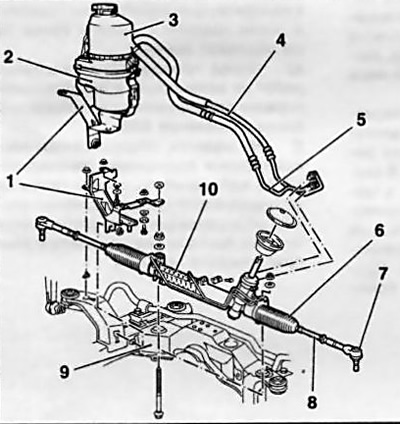
1.3 TRW power steering design
1 Steering pump support bracket
2 Electric steering pump
3 Reservoir
4 Return hydraulic line
5 Pressure hydraulic line
6 Tie rod protective cover
7 Tie rod end
8 Tie rod
9 Subframe
10 Steering gear
Note: Depending on the engine model, the electric power steering can be manufactured by two different manufacturers. The TRW hydraulic booster has a cylindrical reservoir and one-piece oil pump wiring contacts. The ZF hydraulic booster reservoir is made in the form of a truncated cylinder with two flat side faces.
4. Often, during the process of replacing suspension components, one has to deal with fasteners that cannot be released. «sticking» fasteners due to the fact that they are constantly exposed to external influences, are in contact with water, dirt, soot and other substances that contribute to the development of corrosion. In order to facilitate the procedure for giving away such a 'sticky» fasteners, it should be impregnated in advance with a copious amount of penetrating oil or a special agent for corroding rust. Scouring exposed threaded parts of fasteners with a stiff wire brush also helps loosen rusted nuts. In especially severe cases, for release «stuck» bolts / nuts, you can use a chisel / drift and a heavy hammer. Make sure that the chisel / drift does not break, try not to damage the thread with inaccurate blows. Heating a non-retractable fastener and the surrounding surface of the component with a blowtorch or gas burner is also a fairly effective method, although the drafters of this Guide do not recommend resorting to this technology unless absolutely necessary due to its potential danger associated with the possibility of fire and the risk of burns. To increase the torque when releasing fasteners, various kinds of extensions, gates and pipe nozzles are used on them. Sometimes a nut/bolt starts to give in after it has been pre-tightened slightly in a clockwise direction. All fasteners, the release of which required the use of extraordinary measures during assembly, must be replaced!
Note: After giving away, carefully check the condition of the fastener and, if necessary, replace it with elements of the same size.
Attention: Never attempt to straighten deformed suspension and steering components - replace defective parts with new ones!
5. Since the maintenance procedures for the suspension components are performed under the vehicle, care should be taken in advance to raise the vehicle and fix it in a raised position (prepare a reliable jack and props).
Attention: Never carry out any work under the vehicle, which is secured in a raised position only with a jack!
6. Optimum driving performance and minimum tire wear are achieved with proper wheel alignment. In case of uneven tire wear, as well as unsatisfactory road stability, it is necessary to contact a service station to check the suspension geometry and wheel alignment. Checking is carried out only with the help of special equipment.
Precautionary measures
See also Chapter «Controls and methods of operation.
7. An airbag is built into the hub of the steering wheel. To ensure that the airbag deploys properly in a crash, and to avoid the risk of injury from accidental airbag deployment, certain precautions must be taken (see also Chapter 12):
- a) Before starting work on the airbag, or near the places where the SRS wiring is laid, be sure to disconnect the negative battery cable, start work at least one minute after disconnecting the battery - time is needed to discharge the reserve power supply capacitor;
- b) Do not allow the airbag module to exceed 90°C. Do not turn the removed airbag module upside down;
- c) Avoid contact with solvents and detergents on the surface of the module - use only a clean, slightly damp cloth to wipe the steering wheel;
- d) The SRS control unit and airbag modules are sensitive to directional overloads (blows) and after a fall from a height of more than 50 cm must be replaced;
- e) Before carrying out welding work on the vehicle, be sure to disconnect the electrical wiring of the SRS control unit;
- f) On models equipped with passenger airbags, to avoid injury, do not install any accessories or place any foreign objects in the airbag deployment area.
Visitor comments