


Caution: Remember that dust generated during wear of the clutch slave disk friction linings may contain asbestos, which is harmful to health. Do not blow off dust with compressed air and try not to inhale it. Do not use petroleum-based solvents to wipe clutch components - use only special brake cleaners or pure methyl alcohol. Place used rags in a hermetically sealed container.
Note: Below is a detailed description of the procedure for removing/installing the clutch for F17+ and F23 transmissions. The specifics of removing/installing the clutch for F35 and F40 transmissions are given at the end of the Section.
Removal
1. To gain access to the clutch assembly, you must first remove the gearbox.
Note: If the engine was not removed from the vehicle, it is recommended to additionally support it with a jack or install special stands under it.
2. Install the special device KM-6263 (see accompanying illustration), be careful - the lower mounting bolts of the device must be attached to the engine block, and in no case to the oil pan.
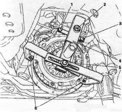
6-2 Installing the KM6263 (4) tool for removing the clutch: 1, 3, 6. Mounting bolts; 2, 5. adjusting bolts of the device
Note: When installing the fixture, the mounting bolts are not tightened, allowing the fixture elements to move.
3. Insert the centering rod (see accompanying illustration) with the appropriate attachment through the hole in the shaft with the pressing mandrel into the central journal of the engine crankshaft and tighten the mounting bolts of the device.
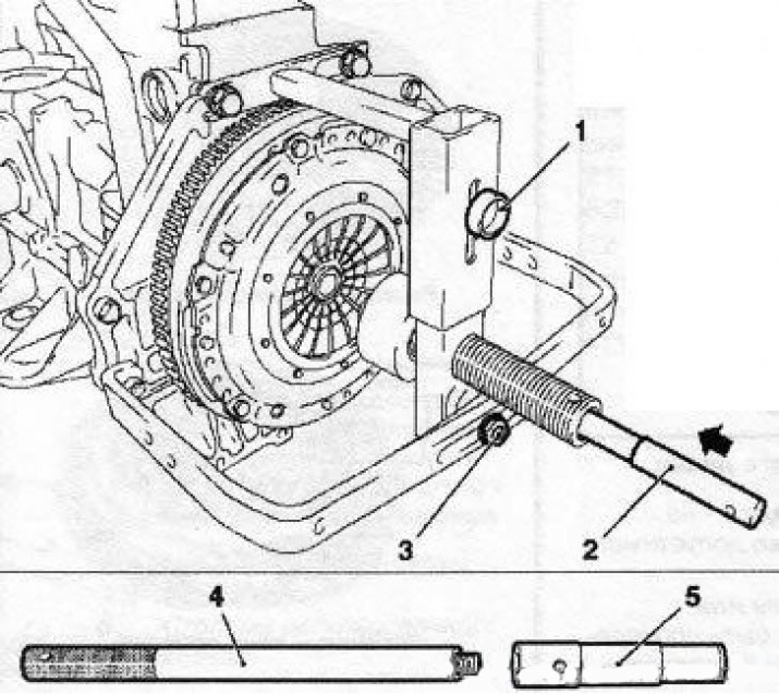
6.3 Installing the centering rod (4) (the illustration shows a clutch from another Opel model): 1. Adjusting bolt of the device; 2. Centering rod assembled with nozzle; 3. Fastening nut; 5. Rod attachment
Note: Each box has its own centering attachment.
If you plan to reuse the same clutch basket, mark its position on the flywheel (in the absence of factory marks).
4. Screw in (clockwise) shaft with the release mandrel until the latter comes into contact with the working edges of the diaphragm spring petals. Continue screwing the shaft in until it stops - the mandrel will compress the spring and separate the clutch discs.
5. Lock the flywheel from turning (see Chapter 2), unscrew the 6 bolts securing the clutch to the engine flywheel in a diagonal order.
6. Smoothly turning inside out (counterclockwise) shaft with the release mandrel, completely release the diaphragm spring. Holding the basket, remove the centering rod and remove the clutch assembly - use the help of an assistant if necessary.
7. After completing the procedure, remove the device from the engine block.
Examination
8. Most often, the malfunction of the clutch is associated with wear of the friction linings of the driven disk. However, it is necessary to carefully examine the condition of all other components of the assembly.
9. Examine the working surface of the flywheel for cracks, traces of overheating, grooves and other damage - replace the flywheel if necessary (see Chapter 2). Also check the condition and evaluate the flatness of the mating surface of the clutch pressure plate (see accompanying illustration).
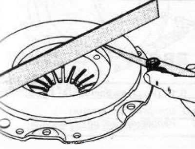
6.9 Measuring the flatness of the mating surface of the clutch pressure plate
10. Assess the degree of wear of the friction linings of the driven clutch disc. The surface of the linings should rise above the rivet heads by at least 1.6 mm. Make sure that all rivets are tightly seated, check the torsion springs/dampers for cracks, signs of deformation and other mechanical damage (see accompanying illustration). Oiling of friction linings most often occurs due to failure of the crankshaft oil seal, damage to the integrity of the oil pan gasket, the sealing element of the actuator cylinder assembly, or the oil seal of the primary shaft of the manual transmission - replace the damaged components
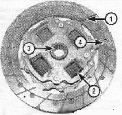
6.10 Assembling the slave disk:
1. Friction linings - in the picture worn below the permissible limit
2. Torsion springs or dampers - should be checked for cracks and signs of deformation
3. Splined hub - must slide freely on the splines of the gearbox input shaft; the splines should not be excessively worn
4. Rivets - used to secure friction linings and when the latter wear excessively, they begin to leave grooves on the working surface of the flywheel
11. It is advisable to replace the release bearing together with the driven disk (see Section 3). If the driven disk is OK, check the condition of the release bearing - the bearing should rotate smoothly, without signs of jamming. The mating surfaces should be absolutely smooth and undamaged, without cracks, burrs or dents. If you are not sure of the bearing condition, replace the slave cylinder assembly (see Section 3).
12. Assess the condition of the machined surfaces and petals of the diaphragm spring of the pressure plate (see accompanying illustrations). If defects are detected, replace the basket assembly. Light polishing traces can be removed with fine-grained sandpaper. A reconditioned clutch assembly can always be purchased on an exchange basis through Opel branded service stations
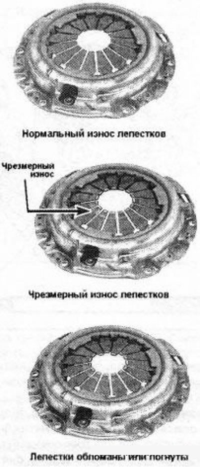
6.12a Examples of diaphragm spring wear
Material provided by this website: OpelBook.ru
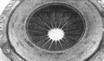
6.12b The friction surface of the pressure plate should be checked for cracks, grooves, deep scratches and signs of overheating
Installation
13. Make sure that the mating surfaces of the flywheel and clutch discs are absolutely clean and dry; if necessary, wipe the working surfaces with solvent.
14. Install the friction disc with the protruding part of the hub away from the flywheel. The disc is usually marked at the factory indicating which side it should be installed towards the flywheel.
15. Install the clutch basket. If you are installing an old basket, make sure that the alignment marks applied during dismantling are correct. Screw in the basket mounting bolts and tighten them only by hand for now to ensure that the driven disk can be centered without any obstacles.
16. Install the KM6263 device, insert the centering rod.
Note: Alignment is necessary so that when installing the gearbox, its input shaft passes through the splines in the disc and enters the guide sleeve in the crankshaft journal.
17. Using a pressing mandrel, completely unload the clutch discs (see above) and, in several steps, in a diagonal order, evenly tighten the basket mounting bolts to the required force. Remove the centering rod and remove the device.
18. Install the gearbox in place.
Features of removal/installation of clutch of transmissions of F35 and F40 brands
19. These models require the installation of an additional device KM-6289 to prevent the clutch disc from turning (see accompanying illustration). Before installation, the device must be adjusted according to the size and type of the clutch, for which insert the removable guide pins and pins with springs into the holes with the corresponding markings. Marks "1" correspond to a clutch diameter of 200 mm, marks "2" - 240 mm (RWD - rear wheel drive models) marks "3" - 240 mm (FWD - front wheel drive models).
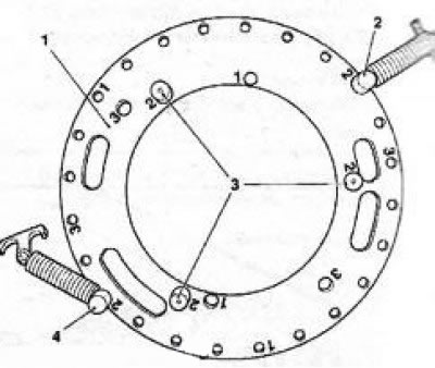
6.19 Device (A) KM-6289:B, D - Pins with springs; C - Guide pins
20. Install the device into the clutch basket - it should fit snugly against the surface of the basket.
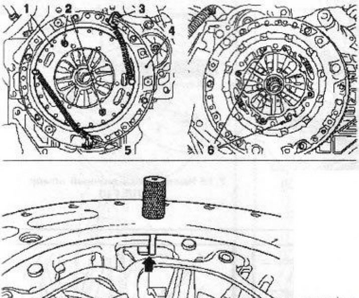
6.20 Installing the KM-6289 device (1) on the clutch basket (4) - the arrow indicates the guide pin in the installed position: 2 - Guide pins; 3, 5 - Spring hooks; 6 - Adjusting ring stoppers
The guide pins must be opposite the stops of the adjusting ring (see accompanying illustration). Fasten the spring hooks to the clutch basket.
21. Install device KM6263.
22. The further procedure for removal and installation is completely analogous to that described above for the F17+ and F23 transmissions.
Visitor comments