
2. Remove the battery from the tray (see chapter 5).
3. Use a clamp to clamp the supply hose connecting the tank to the master cylinder.
Note: The hose should be pinched at a distance of about 5 cm from the cut of the end stretched over the cylinder fitting. Seal the bore in the cylinder immediately to prevent dirt from entering the path.
4. Disconnect the connector (see resist. illustration) electrical wiring, unscrew the 2 mounting bolts and pull the ABS modulator out of the guides.
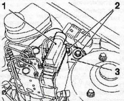
2.4 Removing the modulator (3) ABS: 1. Wiring connector; 2. Fixing bolts
5. Thoroughly wipe the outer surface of the master cylinder and place a wad of rags under it to collect spilled brake fluid.
6. Remove retaining ring (see resist. illustration), release the clutch hydraulic line from the two intermediate holders and pull the hydraulic line together with the damper from the master cylinder assembly, - to minimize the loss of hydraulic fluid, wrap the connector with a rag. Disconnect the supply line hose from the master cylinder. Seal open line ends and connectors immediately to prevent dirt from entering the system.
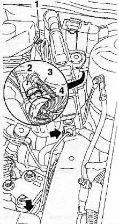
2.6 Removing the hydraulic line of the clutch drive - the arrows indicate the intermediate holders: 1. Feed line; 2. Master cylinder assembly; 3. Retaining ring; 4. Damper; Nut of union connection of a hydraulic line
Attention: To avoid damage to the paintwork, do not allow brake fluid to get on the painted surfaces of the body panels!
7. Remove the bottom facing of the panel of devices under a steering column.
8. Remove the sensor-switch (see conp. illustration) tempostat. Fix the rod of the main cylinder, for which, install the KM-6170 tool into the recesses on the clutch pedal, insert the KM-6202 tool into the hole on the KM-6170 tool, squeeze the rod retainer tabs and pull the clutch pedal towards you.
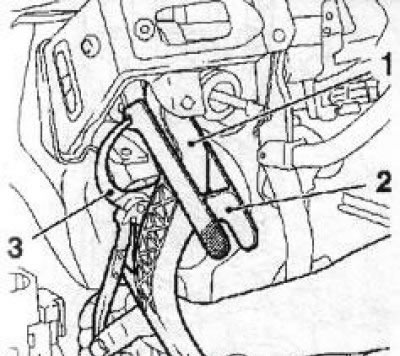
2.8 Installation of special devices KM-6170 (2) and MKM-6202 (3) To remove the fixation of the clutch master cylinder rod: 1. Clutch pedal
Note: Retainer - can be removed and separated from the rod until the master cylinder is removed.
9. On diesel models, wring out the insulation (see resist. illustration) aside and secure it with a plastic wedge.
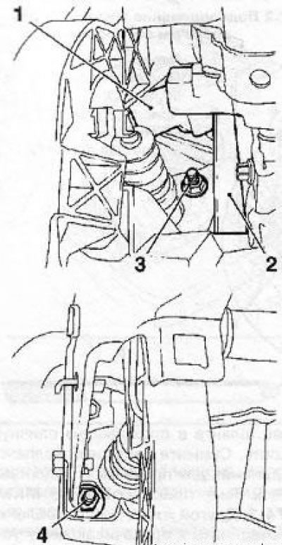
2.9 Nuts (3 and 4) clutch master cylinder mountings: 1. Insulation; 2. Plastic wedge
10. Give two nuts of fastening of the main cylinder to a bulkhead of an impellent compartment (see illustration 2.9). Go to the engine compartment and remove the master cylinder.
11. Installation is made in an order, the return to an order of removal. Finally «pump» hydraulic path to remove air pockets from it (see Section 4).
Visitor comments