
Note: Do not disassemble the master cylinder on vehicles with ABS.
1. Depress the brake pedal several times to dissipate the vacuum in the servomotor unit.
2. Disconnect the electrical wiring of the brake fluid level indicator lamp from the reservoir filler cap.
3. If possible, pump out the brake fluid from the reservoir. This will reduce fluid loss.
4. Place a container under the master cylinder to collect spilled fluid.
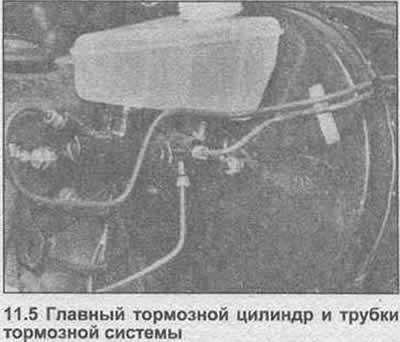
5. Mark the position of the brake pipe, then unscrew the union nuts and disconnect the lines from the master cylinder (photo).
6. Unscrew the front suspension.
7. Turn off mounting nuts and get the main cylinder from racks on the vacuum servo. Be careful not to get brake fluid on body paint.
8. Clean the outer surfaces of the block, then remove the rubber seals from the feed pot.
9. Press the primary piston lightly with a screwdriver, then remove the circlip from the master cylinder bell.
10. Remove the primary piston assembly.
11. Press the secondary piston and unscrew the lock pin from the cylinder body.
12. Get assembly of the secondary piston.
13. Clean all components in methanol and examine them for wear and damage. In particular, check piston surfaces and cylinder bores for scoring and corrosion. If the bore is worn, replace the entire master cylinder or use a repair kit that includes pistons and seals. If the pistons are in good condition, only the rubber seals can be replaced.
14. Check the inlet and outlet ports. When installing new seals to the pistons, use only finger strength to push them into place. The open ends of the insulations must cover the corresponding ends of the pistons.
15. Immerse the secondary piston assembly in clean brake fluid and insert into the cylinder. Press the secondary piston and clamp the lock pin on the housing.
16. Immerse the primary piston assembly in clean brake fluid and insert into the cylinder. Press the piston and install the retaining ring.
17. Install the rubber seals on the nutrient tank.
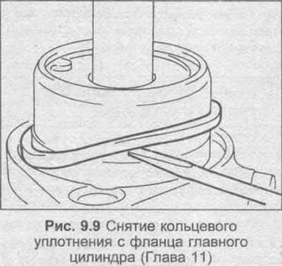
18. If necessary, replace the O-ring on the master cylinder flange.
19. Installation is carried out in the reverse order, but tighten the mounting nuts and connecting nuts with the tightening torque regulated specification and finally bleed the hydraulic system as described in Chapter 13.
Visitor comments