
2. Remove the brake fluid reservoir cap and install a piece of polyethylene to cover the hole to prevent loss of brake fluid when the valve is removed.
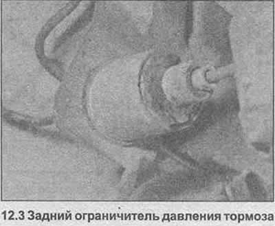
3. Turn off the connecting nuts and disconnect the two pipes of the brake system from the valve (photo). Seal the ends of the tubes.
4. Pull out the stop and remove the valve from the hanger.
5. Installation is carried out in the reverse order, but bleed the rear of the hydraulic system as described in Chapter 13.

Pic. 9.10 Cross-section of the rear brake pressure limiter
1 - casing (valve)
2 - Casing (ball)
3 - Cover
4 - Piston
5 - Coupling ring
6 - Piston seal
7 - Ball
8 - Diaphragm
9 - Pusher plate and pusher
10 - O-ring
A - Entrance
B - Exit
Visitor comments