


General information
1. All models equipped with a manual transmission use a single-plate dry clutch with a diaphragm spring. The hub of the friction (driven) disk is equipped with longitudinal splines that engage with the splines of the transmission primary shaft journal. The friction and pressure plates of the clutch are held in contact with each other by the force developed by the diaphragm spring of the pressure plate. The design of the clutch and its drive is shown in the accompanying illustration.
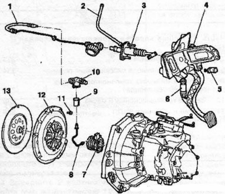
1.1 Design of the clutch and its drive components: 1. Hydraulic line of the clutch release drive path with damper; 2. Hose connecting the master cylinder to the reservoir; 3. Master cylinder; 4. Clutch pedal bracket; 5. Clutch pedal position sensor switch; 6. Eccentric spring (only for manual transmission F35); 7. Assembling the clutch slave cylinder with the release bearing; 8. Hydraulic line; 9. Sealing coupling; 10. Hydraulic line coupling unit; 11. Clutch basket mounting bolt (6 pcs.); 12. Assembling the clutch basket with the pressure plate; 13. Slave (friction) clutch disc
2. The clutch is released hydraulically. The release drive consists of a clutch pedal, a main hydraulic cylinder with a reservoir, connecting lines and a slave cylinder combined with a release bearing, mounted directly on the input shaft of the gearbox (see illustration 1.1).
Note: The reservoir is common to the clutch and service brake system drives.
3. When the corresponding pedal is depressed, the hydraulic pressure in the system tract rises, which is then applied to the release bearing mounted in the slave cylinder. The bearing, under the influence of the hydraulic force, is pressed against the petals of the diaphragm spring of the pressure plate in the clutch basket. By bending, the spring interrupts the contact of the pressure and driven disks, releasing the latter.
Visitor comments