
Attention: Remember that the dust generated during the wear of the friction linings of the clutch disc may contain asbestos, which is harmful to health. Do not blow off dust with compressed air and try not to inhale it. Do not use petroleum-based solvents to clean clutch components - use only special brake cleaners or pure methanol. Store used rags in a sealed container.
Removing
1. To release access to the clutch assembly, you must first remove gearbox.
Note: If the engine was not removed from the car, it is recommended to additionally support the unit with a jack or install special stands under it.
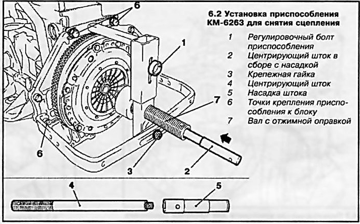
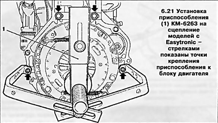
2. Install special tool KM-6263 (see resist. illustration), be careful - the lower mounting bolts of the fixture must be attached to the engine block, and in no case to the crankcase oil pan.
Note: When installing the fixture, the mounting bolts are not tightened, allowing the fixture elements to move.
3. Insert the centering rod with the appropriate nozzle through the hole in the shaft with the forcing mandrel (see illustration 6.2) into the center journal of the crankshaft of the engine and tighten the fixing bolts of the tool.
Note: Each box has its own centering nozzle.
If you plan to reuse the same clutch basket, mark its position on the flywheel (without factory marks).
4. Screw in (clockwise) shaft with a squeezing mandrel until the latter comes into contact with the working edges of the petals of the diaphragm spring. Continue to screw in the shaft until it stops - the mandrel will compress the spring and separate the clutch discs.
5. Turn out 6 bolts of fastening of coupling to a flywheel of the engine.
6. Gently turning (counterclock-wise) shaft with forcing mandrel, fully release the diaphragm spring. While holding the basket, remove the centering rod and remove the clutch assembly - if necessary, have the help of an assistant.
7. At the end of the procedure, remove the tool from the engine block.
Examination
8. Most often, the malfunction of the clutch is associated with the wear of the friction linings of the driven disk. However, you should carefully examine the status of all other assembly components.
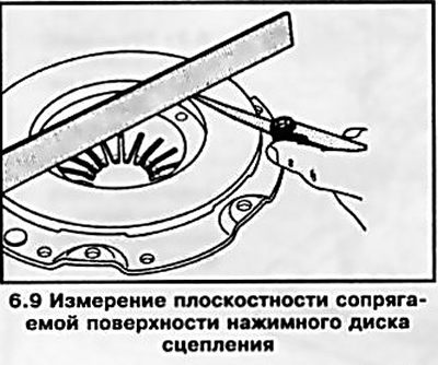
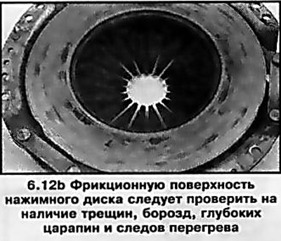
9. Examine the flywheel running surface for cracks, overheating, gouges or other damage - replace the flywheel if necessary (see chapter 2). Also check the condition and evaluate the flatness of the mating surface of the clutch pressure plate (see resist. illustration).
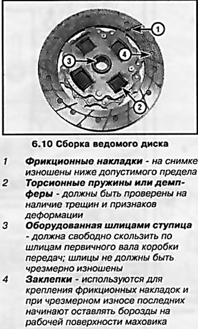
10. Assess the degree of wear of the friction linings of the clutch driven disk. The surface of the overlays must rise above the heads of the rivets by at least 1.6 mm. Make sure that all rivets are firmly seated, check torsion springs / dampers for cracks, signs of deformation and other mechanical damage (see resist. illustration). Lubrication of friction linings most often occurs due to failure of the crankshaft oil seal, violation of the integrity of the oil pan gasket, the sealing element of the slave cylinder assembly, or the oil seal of the input shaft of the manual transmission - replace the damaged components.
11. In tandem with the driven disk, it is also desirable to replace the release bearing (see Section 3). If the driven disk is in order, check the condition of the release bearing - the bearing should rotate smoothly, without signs of jamming. The mating surfaces must be absolutely smooth and undamaged, without cracks, burrs or gouges. If there is no certainty in determining the condition of the bearing, replace the slave cylinder assembly (see Section 3).
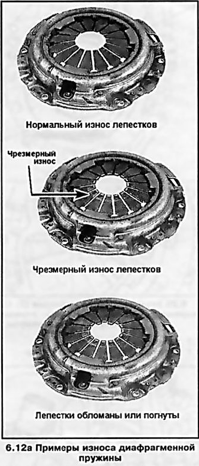
12. Evaluate the condition of the machined surfaces and petals of the pressure plate diaphragm spring (see resist. illustrations). If defects are found, replace the basket assembly. Light polishing marks can be removed with fine sandpaper. Through Opel branded service stations, you can always purchase a remanufactured clutch assembly on an exchange basis.
Installation
13. Make sure that the mating surfaces of the flywheel and clutch discs are absolutely clean and dry; if necessary, wipe the working surfaces with a solvent.
14. Install the friction disc with the protruding part of the hub away from the flywheel. Usually, a factory marking is applied to the disc, indicating which side to the flywheel it should be installed.
15. Install the clutch basket - if an old basket is installed, make sure that the landing marks applied during the dismantling process are aligned correctly. Screw in the basket mounting bolts and tighten them only by hand so far in order to ensure the possibility of unhindered centering of the driven disk.
16. Install the KM-6263 tool, insert the centering rod.
Note: Alignment is necessary so that when installing the gearbox, its input shaft passes through the splines in the disc and enters the guide sleeve in the crankshaft trunnion.
17. Using the squeezing mandrel, completely unload the clutch discs (see above) and in several stages diagonally evenly tighten the basket fastening bolts to the required torque. Remove the centering rod and remove the tool.
18. Reinstall the gearbox.
Features of removal/installation of coupling of the Easytronic system
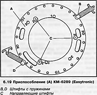
19. On these models, the installation of an additional device KM-6289 is required to fix the clutch discs from turning (see resist. illustration). Before installation, the fixture must be adjusted according to the size and type of clutch. to do this, insert the removable guide pins and pins with springs into the holes with the appropriate markings. Tags «1» correspond to a clutch diameter of 200 mm, marks «2» - 240 mm (RWD), labels «3» - 240 mm (FWD).
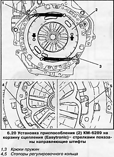
20. Install the tool on the clutch basket - it should fit snugly against the surface of the basket. The guide pins must be opposite the adjusting ring stoppers (see resist. illustration). Attach the spring hooks to the clutch basket.
21. Install the KM-6263 fixture (see resist. illustration).
22. The further procedure for removing and installing is completely similar to that described above for a manual transmission of a conventional type.
Visitor comments