
Note: In the process of removing the gearbox, a large number of parts and assemblies are disconnected - try to remember the location of the bolts and the support brackets fixed by them.
1. The gearbox can be removed in two ways: together with the engine on the subframe (see chapter 2) or separately from the engine. In the second case, special lifting devices are required - a hoist, a winch or a special transverse beam / rod, which is installed on top of the side members, and a set of rigging equipment. Opel service stations use a cross bar and a special universal kit to hold the engine in a suspended position (see chapter 10).
2. Remove intake ducts and air cleaner housing (see chapter 4).
3. Drain gear oil (see Chapter 1, And Section 11 this chapter).
4. Remove the battery from the tray (see chapter 5).
5. Disconnect the electrical wiring from the sensor-switch of the reversing lights and release it from the intermediate clamps on the gearbox housing.
Note: Depending on the configuration and type of manual transmission, other electrical wiring lines may be connected or laid through it - they must also be disconnected.
6. Remove the fitting retaining ring on the top of the clutch dome and disconnect the hose (see resist. illustration) clutch drive. Gently squeezing the lock, put the retaining ring in place in the connector. The sealing ring must be replaced without fail. Seal open ends of tubing and hose immediately to minimize hydraulic fluid loss and prevent dirt from entering the system.
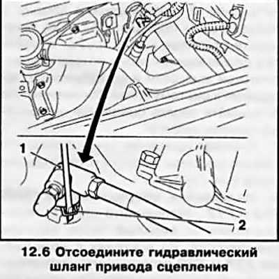
Attention: Do not depress the clutch pedal with the hose disconnected!
7. Remove the front pipe and the middle section of the exhaust system (see chapter 4).
8. On models equipped with F13 and F17 manual transmissions, disconnect the shift rod assembly from the top of the transmission case. On models with gearboxes F23 and F32, disconnect the ends of the cables from the actuator rod of the gearbox, remove them from the support brackets and take them aside.
9. Remove drive shafts (see chapter 8).
10. Hang the power unit using lifting equipment and remove the front subframe (see chapter 10).
11. Turn out fixing bolts and remove the right and left support of the power unit (see chapter 2).
12. Turn out the top bolts of fastening of transmission to the engine (see resist. illustration).
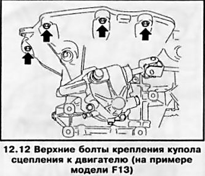
Note: The location of both the upper and lower manual transmission mounting bolts may vary slightly on different models.
13. Turn out fixing bolts and separate an arm of a forward support and a back support of a suspension bracket of the power unit from a coupling dome (see chapter 2).
14. Gradually releasing the hoist, lower the power unit by approximately 5 cm - make sure that the communication lines laid from below are not pinched (hoses and wiring) and make sure that nothing prevents the removal of the box.
15. Remove the lower bolts securing the gearbox to the engine, use the help of an assistant to move the gearbox, separate the clutch dome from the engine block and lower the gearbox (if necessary, a jack can be used for this purpose).
16. Installation is made in an order, the return to an order of removal. Do not forget to replace the seals, refill the gear oil (see Chapter 1 and Section 4), bleed the clutch drive and adjust the gearshift drive (see Section 9).
Visitor comments