
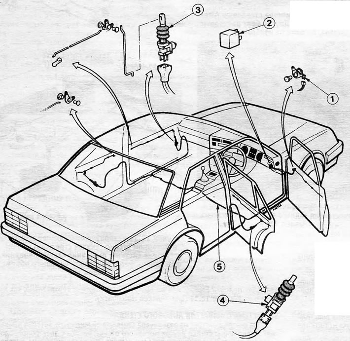
Figure 12.41. Central door locking system components: 1. Driver's door switch; 2. Safety switch; 3. Auxiliary motor (front door); 4. Auxiliary motor (backdoor); 5. Electrical wiring
1. The central locking system ensures, through the use of auxiliary motors and associated electrical wiring, that all passenger doors are locked automatically after the driver's door is locked. Locking or unlocking the driver's door, from the outside or inside, automatically unlocks or locks all other doors.
2. A special safety switch located under the front panel unlocks all doors in the event of an accident or head-on collision.
3. If for any reason the central locking system does not function, all doors will still be able to be unlocked and locked manually.
Driver's door switch - removal and installation
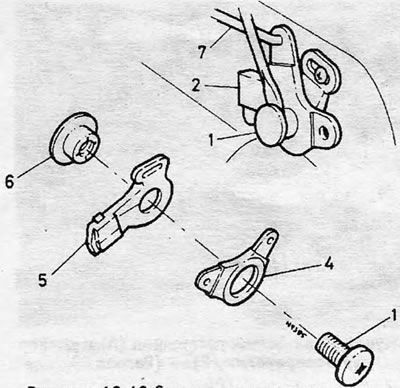
Figure 12.42. Removing the driver's door switch: 1. Central pin; 2. Electrical wiring plugs; 4. Transmission lever; 5. Contact plate; 6. Gasket; 7. Connecting elements
4. Remove the interior door trim panel (see Chapter 11). Remove the waterproof shield around the switch.
5. Disconnect the wiring plug from the switch - all plugs are different sizes, so they cannot be connected incorrectly.
6. Remove the center pin and screw that secures the switch to the door. Remove the switch parts from the door by disconnecting the operating lever from the connecting elements.
7. Reinstall the parts by performing the above steps in reverse order. Before tightening the contact plate screw, place the contact plate at the middle of its stroke in the slot (see Figure 12.43). Check that the switch operates properly before installing the interior door trim panel.
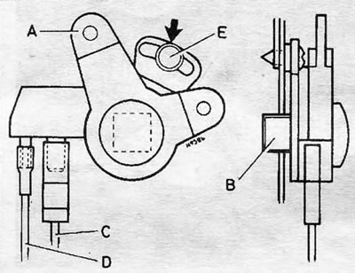
Figure 12.43. Installing the driver's door switch: adjust the slot to the center position (indicated by arrow) → A. Transmission lever; B. Gasket; C. Brown/White Wire; D. Gray wire; E. Contact plate screw
Auxiliary motor - removal and installation
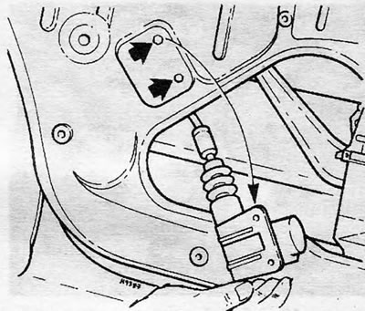
Figure 12.44. Removing the auxiliary motor from the door - arrows indicate mounting bolts
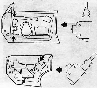
Figure 12.45. Location of auxiliary motors for the central locking system on the front door (up) and on the back door (at the bottom) —Install the motors in the position indicated by the arrows
8. Remove the interior door trim panel (see Chapter 11). Detach part of the water shield to gain access to the motor.
9. Remove the two bolts that secure the motor to the door. Disconnect the mechanical connecting elements and the electrical connector and remove the motor.
10. Reinstall by performing the above steps in reverse order. Use new self-locking special bolts, M6x8mm, available from your GM dealer. Check for proper function before replacing the door trim panel.
Modification of the rear door lock - Hatchback from 1985
11. The rear door lock cylinder can be rotated to one of three positions that affect the operation of the central locking system in relation to the rear door lock, as shown in Figure 12.46.
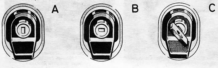
Figure 12.46. Rear door lock modification - central locking system A. Locked - the rear door can be opened without opening the central locking system; B. Unlocked - the rear door can only be opened when the central locking system is open; C. Independent position - the rear door can be opened even if the central locking system is locked. The button and key must be pressed to release the rear door lock. To remove the key, return it to position A or B after the rear door is opened
Safety switch and relay - removal and installation
12. Disconnect the battery.
13. Release the trim tabs that secure the lower driver's side trim panel using a wide-blade screwdriver.
14. Remove the panel, disconnect the electrical wiring plugs and remove the safety switch or relay, depending on what is installed.
15. Reinstallation is carried out by performing the above steps in reverse order.
Visitor comments