
2. The information provided below is intended to provide general instructions for the installation of typical Vauxhall accessories however this does not mean that installation instructions for accessories from other manufacturers should be disregarded.
Cigarette lighter
3. Remove the ashtray and ashtray cover from the front panel.
4. Route the electrical wiring provided in the fuse box.
5. Install the light bulb screen A into the ashtray housing (see Figure 12.52).
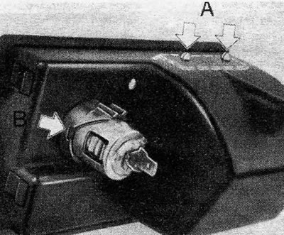
Figure 12.52. Screen for the cigarette lighter light bulb in the ashtray casing. (A) backlight screen and (IN) luminous ring
6. Install the glow ring on the cigarette lighter.
7. Install the cigarette lighter socket into the ashtray housing.
8. Install the light bulb socket into the light ring by pushing the spring of ground wire A under the contact protrusion (see Figure 12.53).
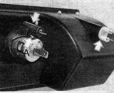
Figure 12.53. Installed cigarette lighterA - Grounding spring The arrows indicate the holders of the cigarette lighter and ashtray light bulbs
9. Install the light bulb holder for the ashtray light bulb.
10. Make the following electrical connections:
- Black - positive wire of cigarette lighter A
- Brown - negative wire of cigarette lighter A
- Black - positive wire of cigarette lighter bulb B
- Black and brown - ashtray light bulb C
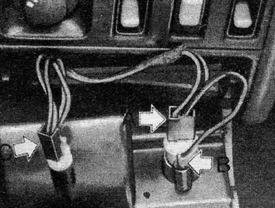
Figure 12.53. Installed cigarette lighter.A - Grounding spring The arrows indicate the holders of the cigarette lighter and ashtray light bulbs
11. Now connect the wires from the cigarette lighter and both bulbs to the spare terminal (15) on the fuse box.
12. Attach the ground wire to the right side of the steering column bracket using self-driving screws and a locking washer in the hole provided.
13. Turning on the ignition (position "ON") and inserting the element into the socket, make sure that the element glows and the light is on.
Watch
14. Remove the decorative plate from the front panel.
15. The clock wiring will include a regular red wire and a regular gray wire.
16. Connect the red wire between the positive terminal of the clock and the terminal (30) on the fuse box (see Figure 12.55).
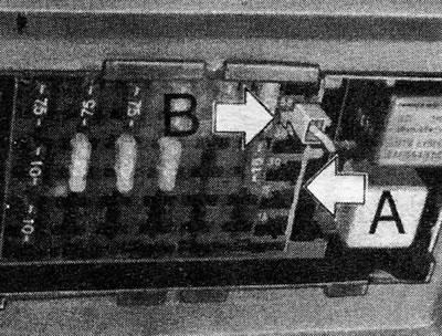
Figure 12.55. Clock electrical connections at the fuse box A - Fuse contact 30; B - Fuse contact 58
17. Connect the gray wire between the clock light bulb and the contact (58) on the fuse box.
18. Connect the ground wire between the clock and the right side of the steering column bracket. Use self-tapping screws and a locking washer in the small hole provided (see Figure 12.56).
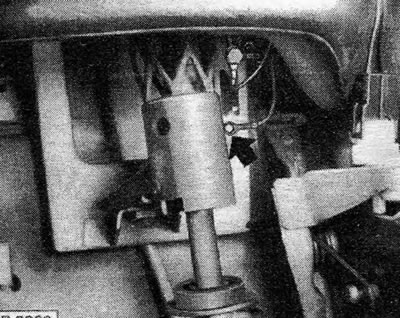
Figure 12.56. Grounding the clock at the steering column bracket
On indicator light ("ON") throttle and switch
19. On later 1.3 models equipped with a manual choke carburetor, a throttle indicator may be installed (provisions "ON").
20. Disconnect the battery.
21. Remove the air cleaner.
22. Disconnect the live throttle cable from the carburetor.
23. Remove the cover from the underside of the front panel (see Figure 12.57).
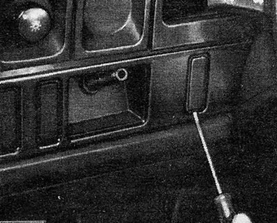
Figure 12.57. Removing the cover from the throttle control mounting plate screws (left hand drive version)
24. Disconnect the locking pin from the throttle control handle.
25. Unscrew the nut securing the throttle control socket.
26. Unscrew and remove the screws and remove the front switch panel (see photo 44.26).
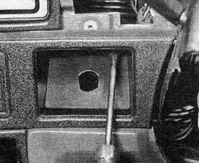
Photo 44.26 Removing the front panel switch panel mounting screw to access the throttle control handle
27. Remove the instrument panel as described in Section 26.
28. Reinstall the light bulb in the indicator socket on the instrument panel.
29. Remove the existing throttle cable assembly and install a new one with a switch.
30. Connect the indicator light to the contact (15) on the fuse box.
31. Connect the throttle switch wire to the light bulb socket.
32. Attach the brown ground wire to the bracket on the right side of the steering column. Use self-tapping screws and a locking washer in the provided hole.
33. Reinstall all previously removed parts and components.
Handbrake indicator and switch
34. Disconnect the battery.
35. Remove the driver's seat.
36. Remove the roller pins and plastic cover on the right seat rail (see Figure 12.58).
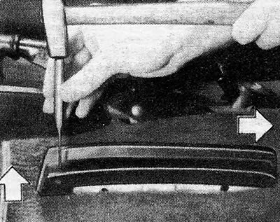
Figure 12.58. Removing the front seat roller pin
37. Remove the door sill molding, the underside cover from under the front panel and the driver's side lower panel.
38. Refer to Chapter 9 and remove the handbrake lever.
39. Screw the switch to the base of the lever and install the lever in place (see Figure 12.59).
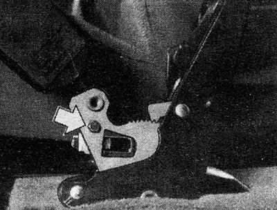
Figure 12.59. Handbrake switch - indicated by arrow
40. Install the wiring between the switch and the rear of the dash panel, running it under the carpet, the threshold and under the trim panel.
41. Remove the instrument panel as described earlier in this Chapter.
42. Install the indicator light and its holder into the rear of the instrument panel (see Figure 12.60).
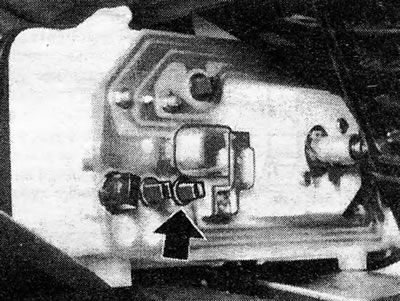
Figure 12.60. Indicator light for engaged handbrake - indicated by arrow
43. Connect the end of the newly installed wire to the multiplug (see Figure 12.61).
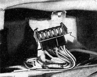
Figure 12.61. Connecting the handbrake engaged indicator to the multi-plug electrical wiring
44. With the ignition on, check that the indicator light comes on when the handbrake is applied. Reinstall the removed parts and components.
Illuminated glove compartment ("glove compartment")
45. Route electrical wiring between the fuse box and the glove compartment. Attach it properly to the back of the front panel.
46. Install the light bulb and holder in the glove compartment, along with the switch.
47. Connect the brown ground wire between the light bulb and the hole provided in the right steering column bracket. Use a self-tapping screw and locking washer for this.
48. Connect the black wire to the contact (15) on the fuse box.
Luggage compartment lighting (Hatchback)
49. Cut a hole in the air ventilation grille from inside the car and strengthen the light bulb (see Figure 12.62).
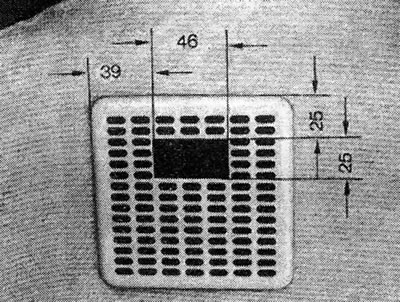
Figure 12.62. Luggage compartment light location - Hatchback Measurements are given in mm
50. Connect the wire from the light bulb to the fuse box, bringing it to the wire that comes from the contact (30). Run the wire under the carpet.
51. Install the plunger switch on the rear door frame and connect it to power and ground (see Figure 12.63).
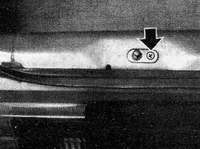
Figure 12.63. Switch on the rear door for luggage compartment lighting The mounting screw is indicated by the arrow
Luggage compartment lighting (Saloon)
52. Install the light bulb holder and light bulb (see Figure 12.64).
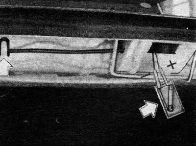
Figure 12.64. Trunk light location The arrows indicate the backlight and wire clamp
53. Install the switch into the mounting hole provided in the left hinge support bracket (see Figure 12.65).
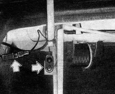
Figure 12.65. Luggage compartment lighting switch and electrical wiring plug - indicated by arrows
54. Connect the brown ground wire to the switch.
55. Connect red wire to red (spare) connector in the adjacent electrical wiring of the vehicle. If a replacement connector is not installed, run a new wire under the carpet at the threshold to the contact (30) on the fuse box (the third terminal, counting from the bottom, protected by fuse No. 4).
Engine compartment lighting
56. Install the light bulb and connect the existing wire to the gray/green connector in the adjacent wiring harness. If there is no such connector, run a new wire between the engine compartment light bulb and the left front parking light (see Figure 12.66).
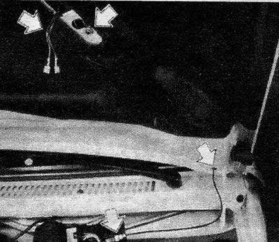
Figure 12.66. Engine compartment lighting. Arrows indicate connections, grounding point and cap
57. Attach the ground wire to the body using a self-tapping screw and locking washer.
58. The engine compartment lighting turns on only when the car lighting is on.
Auxiliary lights
59. Disconnect the battery
60. Remove the lower section of the steering column housing.
61. Remove the cover from underneath the front panel on the fuse box side.
62. Remove the fuse box by pressing the center of its upper part with a screwdriver in the specially provided recess. Push the top of the fuse box and release it from the mounting clips below.
63. Remove the front bumper and grille as described in Chapter 11.
64. Drill mounting holes for auxiliary headlights (25.0 mm) in the bumper in accordance with Figure 12.67.
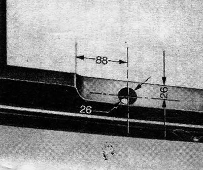
Figure 12.67. Location of the hole for installing auxiliary headlights Measurements are given in mm
65. Install the lamp brackets with the reinforcement plates, spacers, nuts and washers provided in the kit.
66. Install the bumper and radiator grille. Attach the bracket to the grille.
67. Drill a hole in the engine compartment, in the rear upper part and route the electrical wiring (with rubber cap) through it, so that the electrical wiring ends near the fuse box.
68. Attach the relay to the carrier and secure it to the fuse box (see Figure 12.68).
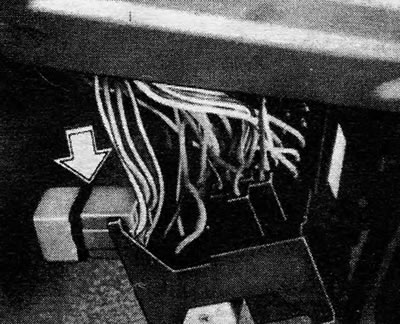
Figure 12.68. Auxiliary headlight relay - indicated by arrow
69. Makes the following connections:
- (A) Red wire, contact (30) to the headlight low beam switch
- (b) White wire, contact (85) to the headlight low beam switch contact
- (V) Ground wire to contact (85)
- (G) Contact (87) to the main beam of the headlights
70. Now connect the wire from the relay contact (30) to the red wire of the headlight low beam switch (see Figure 12.69).
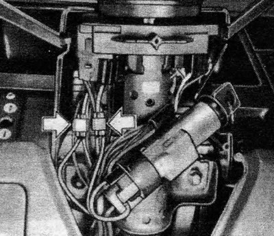
Figure 12.69. Connecting the auxiliary headlight wiring to the headlight low beam switch Connectors are indicated by arrows
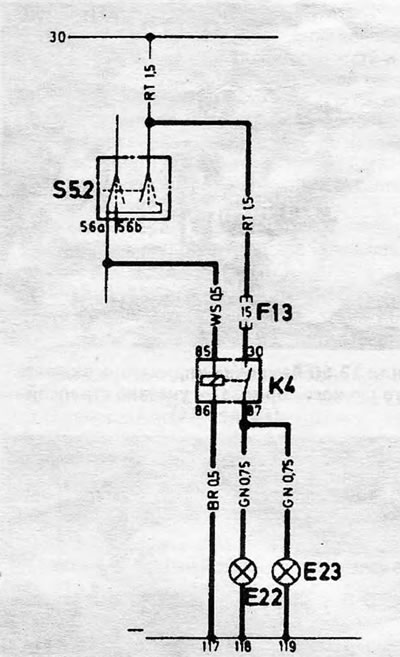
Figure 12.70. Auxiliary headlight circuit diagram E22 Left auxiliary headlight; E23 Right auxiliary headlight; F13 Relay fuse; K4 Auxiliary headlight relay; S52 Low beam switch
71. Connect the wire from the relay contact (85) with white low beam contact wire (56a).
72. Connect the ground wire from the terminal (86) relay to the right steering column mounting bracket using the hole provided for this purpose, a self-tapping screw and a locking washer.
73.Run the power wire from the relay contact (87) through the rubber cap on the top of the engine and connect to the bulb holders.
74. Connect the battery, check the operation of the headlights, and then reinstall all previously removed parts.
75. Adjust the headlight beams, referring to Section 31 for details.
Fog lights
76. Fog lights are usually mounted on the lower spoiler.
77. Drill holes and install headlights according to Figure 12.71.
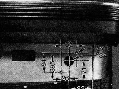
Figure 12.71. Location of the fog lamp mounting holeMeasurements are given in mm
78. Working from inside the vehicle, remove the lower switch panel from the front panel. On vehicles with manual throttle control, the throttle control handle and its socket will need to be removed (see above in this Section), as well as three switch panel screws.
79. Install the fog light switch in a free space and connect it as follows:
- Pin 1 - ground
- Pin 2 - wire from relay contact (85)
- Pin 3 - wire from fuse box pin (15)
- Pin 4 - wire from relay contact (87)
80. Remove the cover from below the front panel, as well as the upper steering column cover.
81. Connect the relay to the fuse box, which must be disconnected so that the relay wiring can be routed to the rear of the fuse box as follows:
- Relay contact (30) from the switch contact (58)
- Relay contact (87) to the fog light wire
- Relay contact (85) from the switch contact (2)
- Relay contact (86) from the headlight low beam switch contact (56a)
82. Connect the wire from the relay contact (86) with a white wire that runs from the headlight low beam switch contact (56a).
83. Release the main lighting switch from the mounting switch panel and connect the wire from the relay contact (30) to the gray/green wire that runs from the light switch contact (58).
84. Connect the ground wire from the contact (1) the fog light switch to the right steering column mounting bracket. For this purpose, a special hole is provided, as well as a self-tapping screw and a locking washer.
85. Drill a hole in the top of the engine compartment and install a rubber cap in it to pass the electrical wiring through it.
86. Pass the wire through this cap, attach it to the contact (87) relay and to contact (A) on the fog lamp (see Figure 12.72).
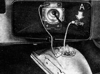
Figure 12.72. Electrical connections for fog lights A See comments in the text
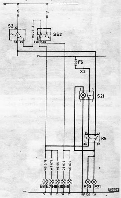
Figure 12.73 Wiring diagram for fog lights E8 Left headlight - high beam; E20 Left fog lamp; E21 Right fog lamp; F6 Fuse box (fuse no. b); K5 Fog lamp relay; S2 Light switch; S21 Fog light switch; S52 Headlight low beam switch; X2 Fuse box (contact no. 15)
87. Connect the wire from the contact (S) on the fog light switch to the wire coming from the relay contact (87).
88. Connect the wires from the fog light switch contact (3) to contact (15) on the fuse box.
89. Reinstall the fuse box, and also secure the fog light switch to the switch panel.
90. Reinstall the steering column cover and lower cover under the dashboard.
91. Connect the battery.
92. Check that the fog lights turn on only when the ignition is on, and that the side lights or low beams are on. When the headlights are on high beam, the fog lights should turn off.
93. Adjust the beam direction of the fog lights.
Visitor comments