


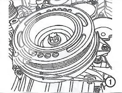
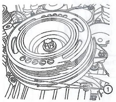
2. Turn the crankshaft pulley in the direction of normal rotation to set the piston of the first cylinder to the top dead center position (marks 1).
3. Remove the cylinder head cover.
4. Without phase shifters: Insert the EN-6340 locking device (1, 2) into the camshaft sprockets.
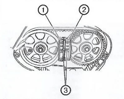
Note: The marks (3) on the retainer must match.
With phase shifters: prepare the right half of the EN-6340 fixing device:
Unscrew two bolts (2).
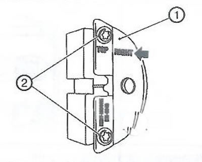
Remove the front panel (1) from the right half of the EN-6340 retaining fixture.
Note: The right half of the EN-6340 locking device can be identified by the inscription "RIGHT".
Insert the left (1) and right (2) parts of the EN-6340 locking tool into the camshaft phase shifters.
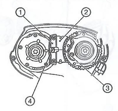
Note: The dot mark (4) on the intake camshaft phase actuator must not be aligned with the groove on the left side of the EN-6340 locking pin (1) during this procedure, but should be slightly higher.
The dot mark (3) on the exhaust camshaft phase shifter must match the groove in the right side of the EN-6340 retainer (2).
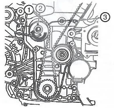
5. Using the Allen key (1), turn the tensioner (2) in the direction of the arrow and remove the EN-6333 locking pin (3).
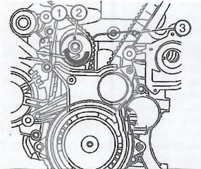
6. Mark the direction of rotation of the timing belt.
7. Install the EN-652 locking tool (1) to secure the flywheel ring gear (2) (or automatic transmission drive disc).
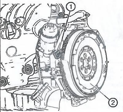
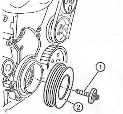
8. Loosen and discard the crankshaft pulley bolt (1).
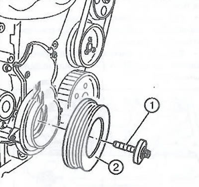
9. Remove the crankshaft pulley (2).
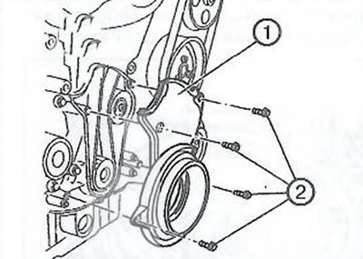
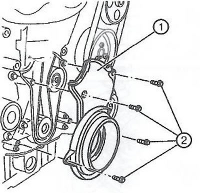
10. Loosen the mounting bolts (2) and remove the lower front timing belt cover.
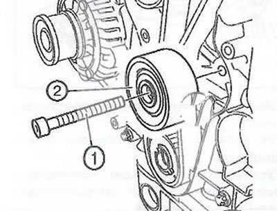
11. Loosen the bolt (1) and remove the timing belt idler pulley (2).
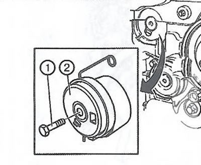
12. Loosen the bolt (1) and remove the timing belt tensioner (2).
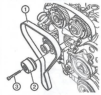
13. Remove the timing belt (1).
14. Secure the timing belt tensioner (2).
15. Remove the EN-652 locking tool from the flywheel to release the crankshaft.
16. Turn the crankshaft 60° (A) against the direction of engine rotation.

17. Unscrew the two plugs (1) and loosen the phase shifter mounting bolts (2).
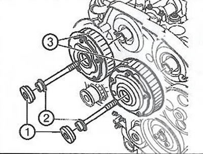
Note: An assistant is required to hold the camshafts by the hexagonal portions.
18. Loosen and dispose of the phase shifter bolts (2) and remove the phase shifters (3).
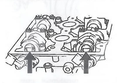
19. Align the horizontal slots of the camshafts (arrows) by turning them by the hexagonal parts so that the EN-6628-A locking tool can be inserted into both camshafts.
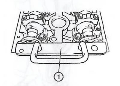
20. Insert the EN-6628-A locking tool (1) into the camshafts.
21. Install the phase shifters (3), then fit, but do not tighten, the new bolts (2).
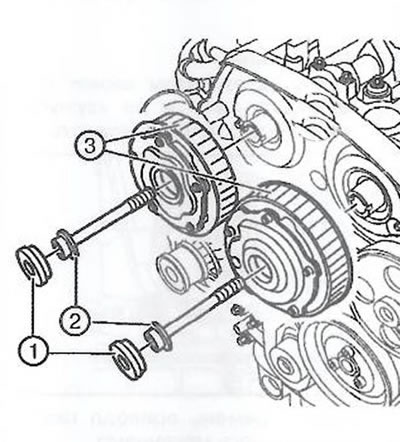
22. Using an assistant to hold the camshafts by the hexagonal parts, tighten the phase shifter bolts (2) in three stages:
- Tighten to 65 Nm.
- Extend to 120°.
- Extend by 15°.
23. After replacing the phase shifter sealing rings, install two plugs (1) and tighten to a torque of 30 Nm.
24. Remove the EN-6628-A locking device.
25. Clean the threads of the timing belt tensioner.
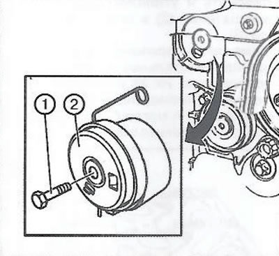
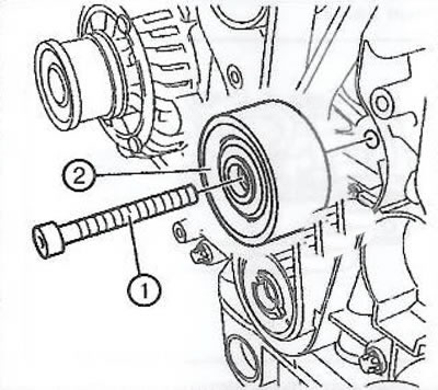
26. Install the tensioner (2) and tighten the new bolt (1) to 20 Nm.
27. Clean the threads of the idler pulley of the toothed belt.
28. Install the idler pulley (2) and tighten the new bolt (1) to 25 Nm.
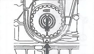
29. Set the engine crankshaft to the top dead center position of the compression stroke of the piston of the first cylinder.
Note: The marks on the crankshaft toothed pulley and on the oil pump housing must match.
30. Install the timing belt of the gas distribution mechanism
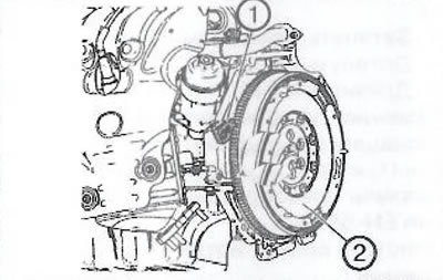
31. Install the EN-652 flywheel locking tool (1) onto the flywheel ring gear (2) (or automatic transmission drive disc).
32. Install the timing belt.
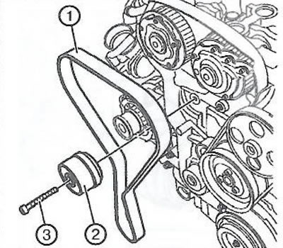
Note: If the belt is reused (for example, when adjusting) make sure that the direction of rotation of the belt is observed.
33. Using the Allen key (1), turn the tensioner (2) in the direction of the arrow and remove the EN-6333 locking pin (3).
34. Install the lower front timing belt cover (1) and tighten the four bolts (2) to 6 Nm.
35. Install the crankshaft pulley (2) and tighten the new bolt (1) in three stages:
- Tighten to 95 Nm.
- Pull to an angle of 45°.
- Extend by 15°.
36. Remove the EN-652 locking tool from the flywheel to release the crankshaft.
37. Remove the EN-6340 locking device.
38. Check the position of the camshaft sprockets:
- turn the crankshaft 720° in the direction of engine rotation using the pulley bolt.
- insert locking tool EN-6340 into camshaft sprockets.
- insert locking tool en-6628-a (1) into the camshafts.
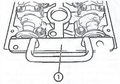
39. Check the position of the crankshaft: the marks on the crankshaft pulley (1) must coincide with the mark on the lower timing belt cover.
40. Remove the EN-6628-A locking device.
41. Install the cylinder head cover.
42. Install the upper front timing belt cover.
Visitor comments