
Disassembly
1. Install EN-6215-5 side fixings (1) on the assembly stand EN-6215-4.
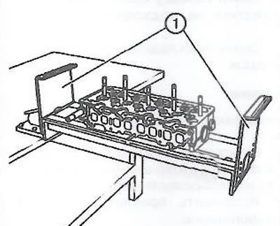
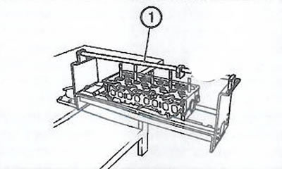
2. Install cross member EN-6215-4 (1).
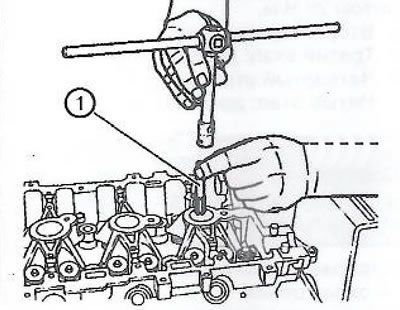
3. It is necessary to clean the threads of the spark plug holes in order to ensure correct and secure installation of the counter supports. Insert tap M14 x 1.25 (1) into the threaded hole and drive slowly along the thread.
4. Turn over the cylinder head.
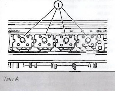
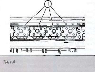
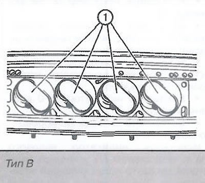
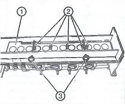
5. Install counter supports (1).
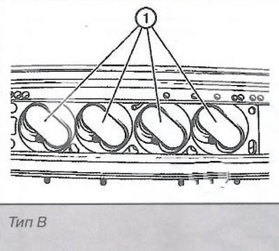
Note. There are two types of counter supports: type A and type B. The correct type must be selected depending on the design of the combustion chamber.
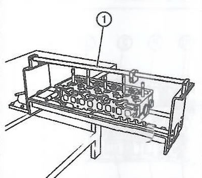
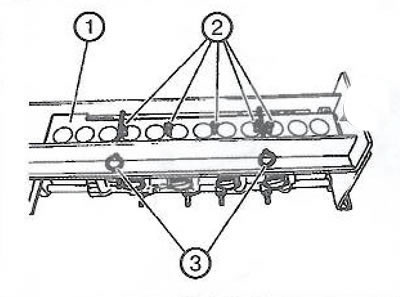
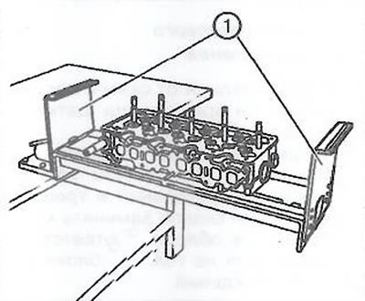
6. Install fixing fixture EN-6167 (1). Connect mounting hardware EN-6215-3 (3) with safety pins. Install fixing bolts (2), then turn the cylinder head over again.
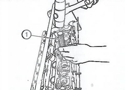
7. In order to prevent damage to the equipment, it is necessary to use the EN-6171 mandrel before cracking the valves (1). Install the mandrel on the valve retainer (a plate of breadcrumbs) and with a short blow of a rubber mallet, loosen the fixation.
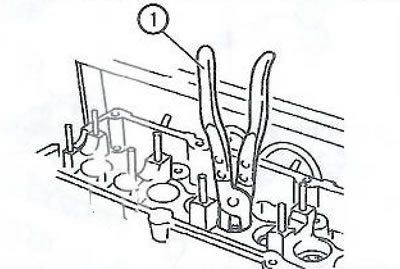
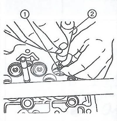
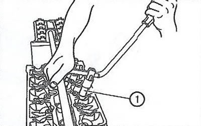
8. Using a special tool (1) compress the valve spring with the poppet to unload the valve cotters, then remove them.
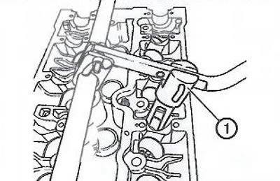
Note. Valve spring compressor (1) must be installed parallel to the valve stem to prevent damage to valve fixtures or parts. If the fixture cannot be installed in parallel, the lever must be adjusted accordingly.
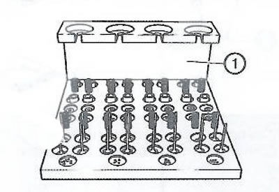
9. Remove the valve disc and valve spring and place them in the appropriate order on the EN-849 assembly shelf. Using the EM-840 puller (1) Remove the valve stem seal from the valve guide with a twisting motion.
10. Dry the rest of the valves in the same way.
11. Remove the valve spring seats from the cylinder head and also place them on the EN-849 assembly shelf (1).
Assembly
Note. Lubricate the valve guides and valve stems with engine oil. Make sure that the valves and their components are installed in their places.
1. Install counter supports (1) the corresponding type.
2. Install fixing fixture EN-6167 (1). Connect mounting hardware EN-6215-3 (3) with safety pins. Install fixing bolts (2), then turn the cylinder head over.
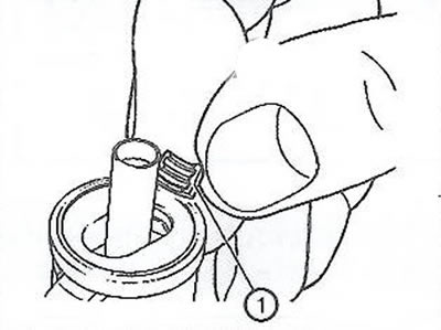
3. Using a suitable mandrel (2) install oil seals (1).
Note. For 5 mm, an EN-958 mandrel will do.
4. Install the spring seats, valve springs and valve plates in the cylinder head.
Note. Make sure the valve springs and poppets are in place.
5. Using a cracker, install the valve crackers. Assemble the dryer in the following order:
- support (6);
- sleeve (5);
- spring (4);
- plunger EN-6086-200-10 (3);
- screw plug (2);
- lever adapter (1).
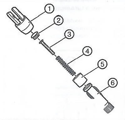
Note. The wrong combination of cracker and plunger can damage the plunger or crackers.
6. Install crackers (1) into a cracker (2), as shown in the figure, and fix them with a grommet.
7. Install lever EN-6086-7 (2) to the adapter (3) with cracker (4) and on the crossbar (1).
8. Gently press the cracker, while you will hear how the valve crackers are installed.
9. In the same way, install crackers on the remaining valves.
10. Remove the cross member (1).
11. Remove holders (1) and disconnect the cylinder head from the mounting stand.
Visitor comments