


Contents: Camshaft sprockets ⬇ Crankshaft sprocket ⬇ Assembly of the tensioning mechanism ⬇ Intermediate pulleys ⬇
Camshaft sprockets
Please note: New sprocket mounting bolts will be required for installation.
Removal
1. Remove the toothed drive belt as described in Chapter 7.
2. Lock the camshaft in one of two ways:
- a) Make a locking tool from two pieces of steel strip (one long, one short), and three nuts and bolts. One of the bolts forms the hinge of the forked tool, the two remaining bolts connect its ends to the sprocket.
- b) Remove the camshaft cover (see Chapter 4) and lock the camshaft with a double-ended wrench (see illustration).
Material copied from the portal opelbook.ru
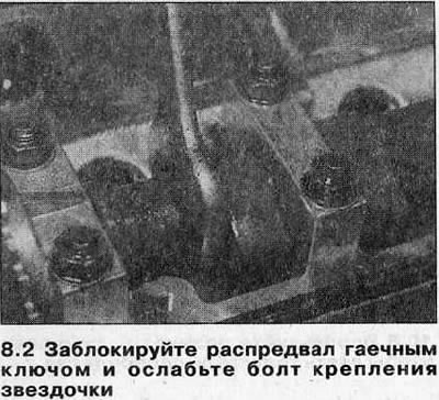
3. Loosen the mounting bolt and remove the sprocket from the end of the camshaft. If the sprocket dowel pin is not securely fastened to the camshaft, remove it and store it with the sprocket.
4. If necessary, remove the second camshaft sprocket using the same method.
Installation
5. Before installation, check the seals for damage and leaks. If necessary, replace them as described in Chapter 9.
6. Place the dowel pin in the working position at the end of the camshaft.
7. Note that the camshaft sprockets are identical and each has two holes for the dowel pin. If the sprocket is installed on the intake camshaft, insert the dowel pin into the hole marked "IN" and if the sprocket is installed on the exhaust camshaft, insert it into the hole marked "EX" (see illustration).
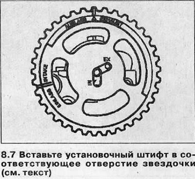
8. Insert the camshaft dowel pin into the corresponding hole in the sprocket, then install the washer and new mounting bolt.
9. Lock the sprocket and tighten its mounting bolt to the tightening torque (see Specifications), then tighten the bolt to the desired angle (see Specifications), using the socket and extension rod. When finished, tighten the bolt to the desired angle (see Specifications). It is recommended to use an angle template for this to ensure accuracy. If a template is not available, apply alignment marks with white paint to the bolt head and flywheel - these will help to ensure that the bolt is turned to the correct angle.
10. Install the timing belt as described in Chapter 7, then install the camshaft cover (see Chapter 4).
Crankshaft sprocket
Please note: A new sprocket mounting bolt will be required for installation.
Removal
11. Remove the timing belt as described in Chapter 7.
12. Lock the crankshaft using one of the following methods:
- a) Use the tool described in step 2, screwing its bolts into the opposite pulley mounting holes.
- b) On manual transmission models, have an assistant select the highest gear and apply the brakes firmly.
- c) If the engine or transmission unit has been removed from the vehicle, lock the flywheel/drive plate (see Chapter 15).
13. Loosen the mounting bolt and remove the sprocket from the end of the crankshaft. Discard the bolt - it is subject to replacement. If necessary, remove the sprocket woodruff key from the crankshaft and remove the spacer gasket.
Installation
14. Place the spacer shim on the crankshaft (where removed), then install the woodruff key.
15. Align the sprocket with the key and install it in the working position with the flange facing out. Install the washer and new mounting bolt.
16. Lock the crankshaft and tighten the sprocket mounting bolt to the tightening torque (see Specifications), then tighten the bolt to the desired angle (see Specifications), using a socket and extension rod. It is recommended to use an angle template for this to ensure accuracy. If a template is not available, apply alignment marks with white paint to the bolt head and flywheel - these will help to ensure that the bolt is turned to the correct angle.
17. Install the timing belt as described in Chapter 7.
Assembly of the tensioning mechanism
Removal
18. Remove the timing belt as described in Chapter 7.
19. Loosen the mounting bolt and remove the tensioner assembly from the engine.
Installation
20. Install the tensioner onto the engine, making sure that the lug on its support plate fits into the hole in the oil pump housing. Install the mounting bolt.
Using a hex key, turn the mechanism lever clockwise toward the stop, then tighten the mounting bolt securely.
21. Install the toothed belt as described in Chapter 7.
Intermediate pulleys
Removal
22. Remove the timing belt as described in Chapter 7.
23. Loosen the mounting bolts and remove the idler pulleys from the engine. If necessary, loosen the pulley bracket and remove it from the cylinder block.
Installation
24. Install the pulley bracket on the cylinder block and tighten the mounting bolts to the specified tightening torque Specifications.
25. Install the intermediate pulleys and tighten the mounting bolts to the specified tightening torque Specifications.
26. Install the toothed belt as described in Chapter 7.
Visitor comments