
Removing
Attention! Allow the engine to cool before removing the cylinder head. At installation use new bolts of fastening of a head of the block of cylinders.
1. Disconnect the negative cable from the battery.
Attention! On models with anti-theft system Opel (ATWS), the negative wire must be separated from the battery terminal within 15 seconds after the ignition is turned off, otherwise the alarm will sound.
2. Drain the cooling system and remove the spark plugs (see related section).
3. Remove the intake and exhaust manifolds. If you are not going to perform any work on the cylinder head, remove it together with the manifolds, having previously performed the following steps (see related section):
- A) Remove the intake duct connecting the air filter to the throttle body.
- b) Disconnect the wiring connectors from the throttle potentiometer, idle speed control, EGR valve, charcoal bypass valve, coolant temperature sensor, oxygen sensor, and ignition control module. Remove the fuel line grounding bolts and release the wiring harness from the mounting brackets. Lift the harness cover off the injectors, then disconnect the knock sensor and crankshaft position sensor connectors and move the cover/wire harness away from the cylinder head.
- V) Depressurize the fuel system, then separate the fuel hoses from the fuel line.
- G) Separate the vacuum hoses and coolant hoses from the intake manifold/throttle body.
- d) Remove the intake manifold bracket bolts and alternator upper brackets.
- e) Disconnect the gas pedal cable.
- and) Remove the front section of the exhaust system.
- h) Disconnect the air hose from the secondary air injection valve on the exhaust manifold.
4. Remove the toothed drive belt as described in Chapter 7, but rotate the crankshaft back approximately 60°before loosening it (4 teeth). This will distribute the pressure of the valve springs evenly along the length of the camshafts and thus prevent the valves from hitting the pistons (see illustration 10.1).
5. Remove the camshafts as described in Chapter 10.
6. Turn off bolts of fastening, - fastening an internal cover of a gear belt to a head of the block of cylinders.
7. Release the mounting brackets and separate the cooling system hoses from the thermostat housing/cylinder head, noting the location of each.
8. Unfasten the crankcase breather tube and remove it from the left wall of the cylinder block. Discard the gasket - it must be replaced.
9. Once again be convinced that separated from a head of the block of cylinders all hoses, tubes and wires.
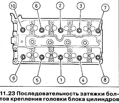
10. Working in the reverse order of their tightening (see illustration 11.23), gradually loosen the cylinder head bolts (a quarter turn in one go), so that the bolts can be unscrewed by hand. Remove bolts along with washers.
11. Remove the head from the cylinder block. If necessary, tap the head gently with a mallet to loosen the block. In no case do not wring the head from the block using any lever. Mark the position of the two alignment pins and remove them if they are loose.
12. Remove the cylinder head gasket - it must be replaced.
Preparing for installation
13. Clean the mating surfaces of the head and cylinder block. Use a soft scraper to remove all traces of gasket and carbon deposits, and clean the piston heads as well. Be especially careful with the aluminum cylinder head as the soft metal is easily damaged. Do not allow dirt to enter the lubrication and water channels - grains of soot can block the oil supply to the camshaft or crankshaft bearings. Use masking tape and paper to cover the water and oil holes and the bolt holes in the cylinder block. To prevent grains from falling into the gap between the cylinder wall and the piston, apply a little grease to this area. After cleaning the piston, turn the crankshaft so that this piston moves down and remove the grease from the cylinder with a clean rag.
14. Check the contact surfaces of the block and the head for the presence of chips, deep scratches and other damage. Small irregularities can be carefully filed off. More serious damage can be repaired by regrinding, but this work should be left to a specialist.
15. If necessary, check the cylinder head for deformation with a ruler. See Section 2C if it is needed.
16. Make sure that the holes for the cylinder head bolts in the crankcase are clean and remove oil from them using a syringe or sponge. If liquid or oil remains in the holes, the hydraulic pressure that will build up when the bolts are tightened will cause the block to crack.
17. Replace bolts of fastening of a head of the block of cylinders irrespective of their condition.
Installation
18. Make sure the crankshaft is still at approximately 60°BTDC and wipe the mating surfaces of the head and block.
19. Make sure the alignment pins are in position (see illustration).
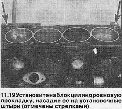
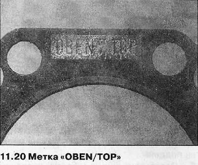
20. Install a new head gasket on the cylinder block with a mark «OBEN» (or «TOR») up to the front of the engine (see illustration).
21. Carefully install the cylinder head, guiding it along the pins.
22. Install the washers on the new cylinder head bolts, then carefully insert the bolts into position and tighten only by hand so far.
23. Working in the sequence shown, progressively tighten all bolts to the Stage 1 torque specified specifications (see illustration).
24. In the same sequence, tighten the bolts to the Stage 2 corner (see specs), using the socket and extension rod. An angle gauge is recommended to ensure accuracy.
25. Working in sequence again, tighten all bolts to Stage 3 angle (see specs).
26. In the same sequence, tighten the bolts to the Stage 4 corner (see specs).
27. In the same way, perform Step 5 tightening (see specs).
28. Make sure that the contact surfaces are clean and dry, then install the breather tube on the cylinder block and tighten the fastening bolts with the tightening force regulated by the Specifications.
29. Connect the cooling system hoses and attach them with brackets.
30. Establish bolts of fastening of an internal cover of a gear drive belt and clamp them with the tightening force regulated by Specifications.
31. Install the camshafts as described in Chapter 10.
32. Align all alignment marks of the sprockets to bring the camshafts and crankshaft to the TDC position, then install the toothed belt as described in Chapter 7.
33. Install the camshaft cover and toothed belt cover (see chapters 4 and 5).
34. Install the intake and exhaust manifolds and connect the wiring (see related section).
35. Make sure all tubes and hoses are securely attached, then top up coolant level and install spark plugs (see related section).
36. Connect the battery, then start the engine and check its joints for leaks.
Visitor comments