
Attention! When installing, you will need new bolts securing the balancer block.
Removing
1. Remove the sump and downpipe/oil pump strainer (see chapter 12).
2. Install the socket on the crankshaft sprocket bolt and rotate the shaft in the direction of rotation so that the notch on the pulley rim is aligned with the pointer on the timing belt cover. This will bring piston #1 to TDC. In this case, the chamfers at the ends of the balancer shafts should stand in the same plane (see point 5).
3. Evenly and gradually loosen and remove the mounting bolts, then remove the balancer block from the base of the cylinder block along with the spacer. The shim is used to adjust the gap between the teeth of the gears of the balancer block (see point 10).
Installation
4. If any procedures were performed on the crankshaft or a new balancer is being installed, it is necessary to adjust the gap between the teeth of the balancer gears before installation. If the old balancer block is installed and the crankshaft has not been reground, you can install the block with the old spacer without checking the gear engagement gap.
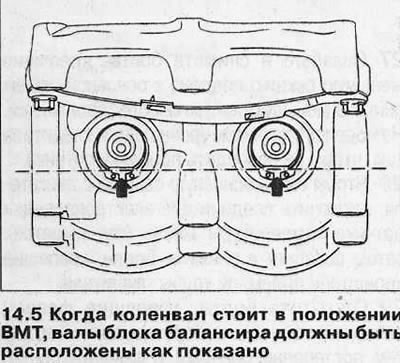
5. Check that the notch on the crankshaft pulley is still level with the pointer on the cover, then turn the gears of the balancer block so that the chamfers on the ends of the shafts are facing down and in a horizontal plane (see illustration).
6. Place a spacer on top of the balancer block, then install the balancer onto the cylinder block. Make sure the balancer shaft gear is engaged with the crankshaft gear and install new mounting bolts.
7. Tighten all bolts by hand, then check that the crankshaft pulley mark and balancer shaft chamfers are still correctly positioned. If this is not the case, remove the balancer assembly and make any necessary adjustments, then reinstall the assembly.
8. Working in a diagonal sequence, tighten the mounting bolts to the torque (see specs). In the same sequence, tighten the bolts to the required angle (see specs). It is recommended to use an angle template for this to ensure accuracy.
9. Install downpipe/oil pump strainer and sump as described in Chapter 12.
Adjustment
Attention! The following procedure can only be done accurately with the Opel KM-949 special tool and a micrometer.
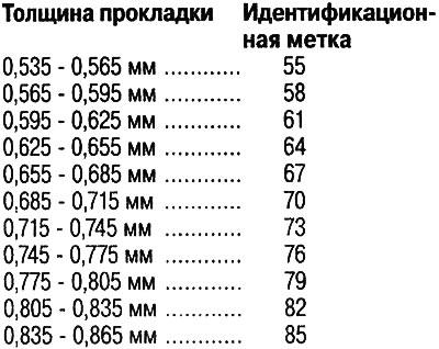
10. To check the gap between the gear teeth of the balancer block (see point 4) proceed as follows. The engagement clearance depends on the thickness of the spacer installed between the balancer and the cylinder block. The thickness of the commercially available gaskets varies as follows (thickness can be determined by measurement or by identification mark).
11. The engagement clearance is measured after the balancer is installed on the cylinder block. If installing a new balancer block, purchase the thickest spacer (identification mark 85) and install the balancer on the cylinder block using the old mounting bolts (see points 5-8).
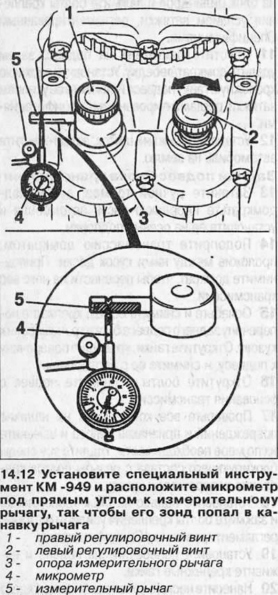
12. Bring the piston of cylinder No. 1 to TDC (see point 2) and install the special tool KM-949. Place the measuring arm against the right shaft (intake manifold side) to a horizontal position, then screw the knurled adjusting screws into the balancer shafts and tighten them securely. Position the micrometer at right angles to the measuring arm so that its probe is in the groove of the arm (see illustration).
13. Using the adjusting screw, turn the left balancer shaft (exhaust manifold side) fully clockwise, then set the micrometer to zero. Turn the shaft counterclockwise as far as it will go and record the value obtained on the micrometer scale (it shows the displacement of the lever).
14. Move the micrometer probe away from the measuring arm, then rotate the crankshaft 45° (balancer shafts turn 90°). Loosen the right adjusting screw, return the measuring arm to the horizontal position and tighten the screw securely, then measure the engagement gap again.
15. Repeat this procedure two more times to get four clearance measurements.
16. All four results should be within the range of 0.02-0.06 mm. If at least one of the measurements goes beyond these limits, adjustment is necessary.
17. In this case, remove the balancer from the cylinder block and remove the spacer. Determine the thickness of the last (see point 10). The engagement clearance decreases when a thinner shim is installed and vice versa. Calculate the required gasket thickness. For example, if a gasket with an identification mark is installed «67» and while the engagement gap is 0.07 mm, replacing the gasket with a component with a mark «64» will reduce the gap by approximately 0.02 mm.
18. Obtain a spacer of the correct thickness, then install the balancer block as described in steps 5-9.
Visitor comments