
Removing
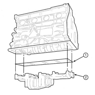
Some 2.0L DOHC engines equipped with a balancing block (2), installed between the cylinder block and the main section of the oil pan. The block consists of two counter-rotating balance shafts driven by the crankshaft.
1. Remove the oil pickup pan assembly (see Removal and installation of the oil pan).
2. Loosen the mounting bolts one by one in several steps, unscrew them and remove the balancing mechanism from the cylinder block assembly with an adjusting shim (1), installed between the balancing assembly and the cylinder block.

Installation
If maintenance work was performed on the crankshaft, or the engine balancing mechanism was replaced, it will be necessary to adjust the meshing play of the drive gear teeth before installing the latter.
When installing the previous mechanism, provided that no work was done on the crankshaft, there is no need for this adjustment.
Competent adjustment of the gear engagement outside the conditions of the original Opel service station can only be done using the special tool KM-949.
1. Prepare the special tool. Bring the engine to the TDC position of the end of the compression stroke of the piston of the first cylinder (see Bringing the piston of the first cylinder to the position of the top dead center of the compression stroke (TDC).
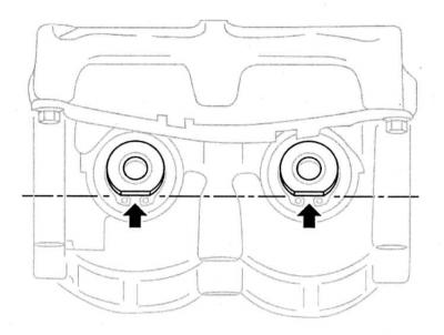
2. Turn the gears of the balancing shafts so that the trunnions of the latter are flattened down and strictly horizontal.
3. Install the shim on the top mating surface of the balance assembly. Press the assembly against the cylinder block. Make sure that the mechanism shaft gear is engaged with the crankshaft gear, then screw in the mounting bolts and tighten them to the required torque.
4. Attach tool KM-949. Screw a long knurled bolt into the end of the balance shaft trunnion from the side of the inlet pipeline. Set the measuring arm to position «9 o'clock», when viewed from the rear of the engine. Tighten the bolt by hand.
5. Screw the short knurled bolt into the end of the second balancing shaft. Tighten the bolt by hand.
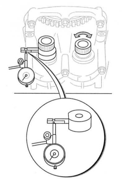
6. Install a dial gauge on the balancing assembly or cylinder block so that its plunger rests against the measuring arm between the recesses on its smooth surface of the arm.
7. For the knurled bolt, turn the left balancing shaft clockwise until it stops and reset the meter.
8. Turn the shaft counterclockwise as far as it will go, read the instrument readings and record the result.
9. Having received the results of all four measurements, turn the crankshaft by the bolt of its cogwheel clockwise so that the measuring lever is on «inlet» balance shaft is in position «for 6 hours». Loosen the knurled bolt and move the lever to the position «at 9 o'clock». Repeat the measurement and take two more readings, turning the balance shaft each time.
10. If the result of at least one of the measurements is outside the allowable range (see Specifications), therefore, the gear engagement play needs to be adjusted. Adjustment is achieved by selecting spacers installed between the cylinder block and the balancing assembly. Gaskets are marked according to thickness (see Specifications), - the code is stamped directly on the surface of the gasket.
11. Having determined the size of the gap and knowing the thickness of the old gasket, you can calculate the thickness of the required replacement gasket. Gaskets are produced with a thickness step of 0.02 mm. Let, for example, the size of the gap with the gasket installed «70» was 0.08 mm. If the gasket is replaced with No. 67, the gap will be reduced to 0.06 mm.
Installation of several gaskets at once is not allowed!
12. Having picked up the gasket and installed the balancing block assembled with it, make a series of control measurements. If necessary, repeat the gasket selection procedure.
13. Remove the gauge and unscrew the bolts from the ends of the balancing shafts.
14. Install the oil pan (see Removal and installation of the oil pan).
Visitor comments