


Removal
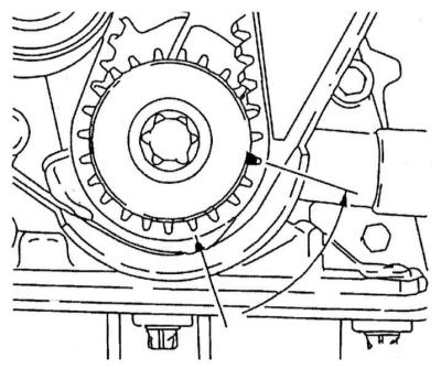
1. Remove the timing belt (see Removal and installation the timing belt). Before loosening the timing belt, move the engine out of the TDC position by turning the crankshaft 60° counterclockwise to equalize the distribution of the forces developed by the valve springs and to prevent the camshafts from turning, which could damage the internal components of the mechanism as a result of the pistons coming into contact with the valves.
2. Remove the camshaft gears (see Removal and installation of crankshaft/camshaft gears and intermediate rollers).
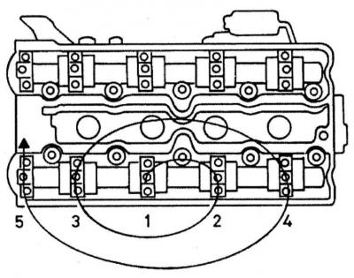
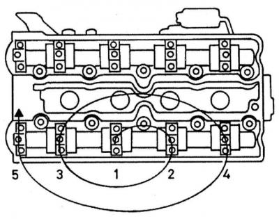
3. Start with the intake camshaft: move in a spiral from the edges inward (in the reverse order shown in Illustration 26.15), in several steps, half a turn at a time, evenly loosen the shaft support cover mounting bolts (the force developed by the valve springs with this approach will also be weakened evenly and gradually). Once the spring action has been neutralized, unscrew the bolts by hand and remove the covers, being careful not to let the guide bushings of the covers fall out (if any are provided).
A — Tightening order of the exhaust camshaft support cap fasteners (for the intake shaft the order is the same)
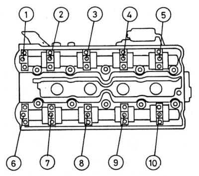
B — Numbering order of camshaft support bearing caps
C — Identification markings must be clearly visible on both the caps and the head surface
A.
B.
C.
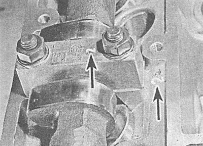
The bearing caps are numbered in order from 1 to 5 (intake shaft) and from 6 to 10 (exhaust shaft) and during assembly they must be installed strictly in their original places. Be careful not to lose the guide bushings of the covers (where are they installed).
Failure to exercise caution when loosening the fasteners of the support bearing caps can result in their mechanical damage, which will lead to the need to replace the cylinder head. Loosen the caps carelessly, they can break. If at least one cap is broken, the entire cylinder head will have to be replaced - during manufacture, the caps are processed together with the head and are not supplied to the spare parts market individually.
4. Lift the camshaft and remove it from the engine, carefully remove the oil seal.
5. Proceeding in a similar manner, remove the exhaust camshaft.
6. Prepare 16 small transparent plastic bags or clean plastic cups and label them according to the valve numbers. Using a rubber suction cup, remove the tappets from the head and place them in the appropriate cups.

To prevent oil from leaking out of the hydraulic lifters, place the tappets with the working ends facing up.
Examination
1. Carefully check the condition of the camshaft bearing necks and cams. Replace the shaft if any scuffs or scratches are detected. Also check the condition of the working surfaces of the plain bearings in the supports of the gas distribution mechanism housing. In case of detection of defects that cannot be eliminated, you will have to replace the cylinder head (see above Removal).
2. Alternately placing the camshafts in the prisms, use a plunger-type dial gauge to determine the value of their radial runout (by bearing journals). If the measurement results are outside the permissible range (see Specifications) the camshaft must be replaced.
3. Check the condition of the tappets and their mounting seats in the head. If signs of excessive wear of the working surfaces, cracks, scoring and other damage are detected, replace the tappets.
The tappets should also be replaced if the valve mechanism has recently been accompanied by increased noise levels.
Installation
1. Lubricate the tappets with clean engine oil and carefully place them in their seating positions in the cylinder head.
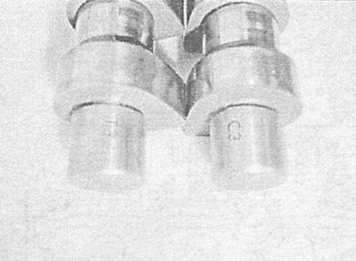
C3 - Intake shaft
T3 - Exhaust shaft
2. After lubricating with molybdenum-containing grease, place the camshafts in their beds.
On 1.8L engines, the intake shaft is marked C3, the exhaust shaft is T3. Make sure that the crankshaft is still turned 60° before TDC and turn the camshafts so that the cams of the first cylinder are turned with the working lugs upward. Temporarily place the gears on the journals of the shafts and make sure that the TDC timing marks are correctly aligned with the corresponding marks on the head (see Bringing the piston of the first cylinder to the top dead center position of the compression stroke (TDC).
3. Make sure that the mating surfaces of the bearing caps and the cylinder head are absolutely clean and dry. Lubricate the journals and cams of the shafts with clean engine oil.
4. Apply a layer of sealant to the mating surfaces of the outer covers and the cylinder head on both sides of the seal seats.
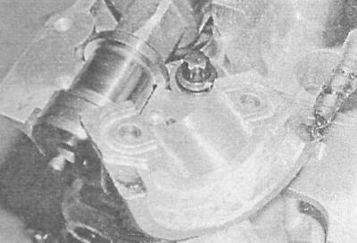
5. If equipped, make sure the guide bushings are in place, then install the covers.
The covers are numbered in ascending order from the front to the rear, and the corresponding numbering is also applied to the top surface of the head - the markings should be read when looking at the engine from the front.
6. Tighten the intake manifold cover bolts first by hand, then, moving in a spiral from the center outward, in several steps, half a turn at a time, evenly (in order to ensure gradual and uniform compression of the valve springs) tighten them until the caps are pressed against the head. Then, in the same order, tighten the fasteners with the required force.
Failure to tighten fasteners correctly may result in damage to the caps and the need to replace the cylinder head (see above Removal).
7. Proceeding in a similar manner, tighten the fasteners of the exhaust shaft support bearing caps.
8. Install new seals (see Replacing camshaft seals).
9. Install the camshaft gears (see Removal and installation of crankshaft/camshaft gears and intermediate rollers).
10. Ensure that the TDC timing marks on the crankshaft and camshafts are correctly aligned, then install the timing belt (see Removal and installation the timing belt).
11. Install the timing cover and timing drive covers (see Removal and installation the timing cover and Removal and installation the timing belt cover).
Visitor comments