


Proceed with the work only after the engine has completely cooled down!
Removal
All engines
1. Release the pressure in the fuel system (see Chapter Power and exhaust systems). Disconnect and remove the battery (see Chapter Engine electrical equipment).
2. Drain the cooling system (see Chapter Cooling and heating systems).
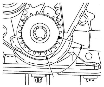
3. Remove the timing belt (see Removal and installation the timing belt). Before loosening the timing belt, move the engine out of the TDC position by turning the crankshaft 60° counterclockwise to equalize the distribution of the forces developed by the valve springs and to prevent the camshafts from turning, which could damage the internal components of the mechanism as a result of the pistons coming into contact with the valves.
Engines 1.4, 1.6 and 1.8 l
1. Remove the intake manifold and exhaust manifold (see Chapter Power and exhaust systems). If the cylinder head is not serviceable, it can be removed as a complete assembly with the pipe and manifold:
2. Disconnect the exhaust manifold exhaust pipe assembly with the support bracket from the exhaust manifold
3. Disconnect the electrical wiring from the lambda probe.
4. Disconnect the wiring from the crankshaft position (CKP) sensor.
5. Remove the timing cover (see Removal and installation the timing cover).
- Remove the camshaft sprockets (see Removal and installation of crankshaft/camshaft gears and intermediate rollers).
- Remove the bolts securing the rear timing cover to the timing mechanism housing.
- If you have not already done this, disconnect the electrical wiring from the control unit (ECU) on the left side of the cylinder head.
- Loosen the clamps and disconnect the coolant hoses from the thermostat housing.
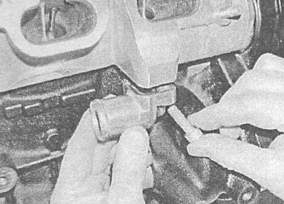
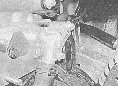
6. In order to remove the coolant from the cylinder block, disconnect the hoses running from the heater heat exchanger to the intake manifold (see Chapter Cooling and heating systems), - as soon as the fluid stops leaking, restore the original hose connections. Collect any spilled fluid with paper towels. Remove the two TORX-type head bolts and separate the hose connection flange from the rear of the cylinder head.
A — Removing the cooling system hose connection flange (1.8L engine)
B — Removing the cooling system hose connection flange (1.4 and 1.6 l engines)
A.
B.
7. On 1.4L and 1.6L engines, release the two PCV hoses from the ECU support bracket on the left side of the head.
8. On 1.8L engines, remove the mounting bolt and move the engine oil dipstick guide tube to the side.
9. Make sure that all hoses, tubes, wires and other communication lines are disconnected and do not interfere with the removal of the cylinder head.
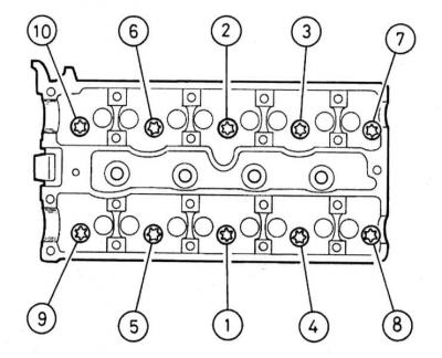
10. Working in the reverse order to that shown, gradually, a quarter turn at a time, evenly loosen the cylinder head mounting bolts until they can be unscrewed by hand. Remove the bolts from the head complete with their washers.
11. Lift up and separate the cylinder head from the block; if necessary, tap it on the sides with a soft-faced hammer.
Never pry the head with a lever to avoid damaging the mating surfaces! Mark the position of the two guide bushings, remove them from the block and put them in a safe place.
12. Remove the sealing gasket - do not discard the gasket yet in order to identify the new one.
2.0L Engines
1. Remove the intake manifold and exhaust manifold (see Chapter Power and exhaust systems). If the cylinder head is not serviceable, it can be removed as an assembly with the pipe and manifold.
2. Remove the timing cover (see Removal and installation the timing cover).
3. Remove the camshaft gears (see Removal and installation of crankshaft/camshaft gears and intermediate rollers).
4. Unscrew the bolts securing the rear timing cover to the timing mechanism housing.
5. If the intake manifold will not be removed, remove the generator/manifold support brackets and move the generator rearward.
6. Disconnect the accelerator cable (see Chapter Power and exhaust systems).
7. Disconnect the brake booster servo vacuum hose from the intake manifold.
8. Disconnect the fuel lines from the fuel line.
9. Loosen the mounting clamps and disconnect the cooling system hoses from the heater heat exchanger and throttle body.
10. If you have not already done so, disconnect the fuel injector wiring and move it to the side.
11. Remove the exhaust camshaft (see Removal and installation of camshafts and valve lifters, checking the condition of components).
12. Make sure that all hoses, tubes, wires and other communication lines are disconnected and do not interfere with the removal of the cylinder head.
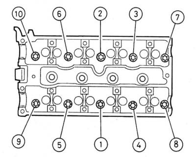
13. In the reverse order to that shown, gradually, one third of a turn at a time, using a 12-sided TORX T55 (KM-2355) key, loosen the cylinder head mounting bolts evenly enough to allow them to be unscrewed by hand. Remove the bolts from the head complete with their washers.
14. Lift up and separate the cylinder head from the block; if necessary, tap it on the sides with a soft-faced hammer.
Never pry the head with a lever to avoid damaging the mating surfaces! Mark the position of the two guide bushings, remove them from the block and put them in a safe place.
15. Remove the sealing gasket - do not discard the gasket yet in order to identify the new one.
Preparing for installation
Cm. Removal and installation the cylinder head.
Installation
All engines
1. Make sure the crankshaft is still rotated 60° before TDC.
2. Using a clean cloth, wipe the mating surfaces of the block and head dry.
3. Make sure both guide bushings are installed in their sockets.
4. Place a new sealing gasket on the mating surface of the cylinder block, with the "OBEN/TOP" marking facing up.
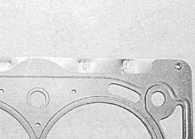
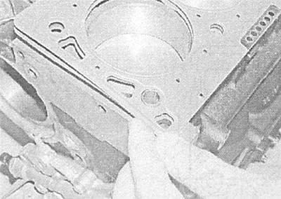
5. Install the head on the cylinder block - make sure that the guide bushings fit correctly into the receiving sockets.
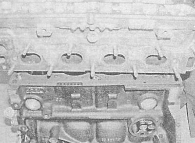
6. Place washers on the NEW cylinder head bolts, then carefully install the bolts and tighten them finger tight.
7. Acting in a strictly defined sequence, in several steps evenly, tighten the bolts with the force of the 1st stage.
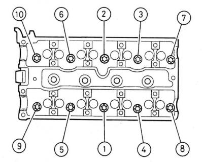
8. In the same order, tighten the bolts to the corners first 2nd, then 3rd, 4th stage and 5th, use a protractor attachment, or apply reference marks with paint or a marker.
Engines 1.4, 1.6 and 1.8 l
1. Restore the original connection of the coolant hoses - do not forget to replace the sealing ring of the flange connection on the back of the head. Make sure that the fastening bolts / clamps are securely tightened.
2. Restore the original wiring connection. Make sure that the harnesses are laid correctly and that they are securely fastened with all the provided fasteners.
3. Install the rear timing belt cover, screw in the mounting bolts and tighten them to the required torque.
4. Install the camshaft gears (see Removal and installation of crankshaft/camshaft gears and intermediate rollers).
5. Bring the engine to the TDC position (see Bringing the piston of the first cylinder to the position of the top dead center of the compression stroke (TDC)) and install the timing belt (see Removal and installation the timing belt).
6. Install the timing gear and timing drive covers (see Removal and installation the timing cover and Removal and installation the timing belt cover).
7. Install the intake manifold and exhaust manifold (see Chapter Power and exhaust systems).
8. Install the wheel, lower the vehicle to the ground and tighten the wheel bolts to the required torque.
9. Check the correct routing and connection of the cooling system hoses.
10. Make sure that all hoses are correctly routed and securely connected, then fill the cooling system (see Chapter Cooling and heating systems).
11. Reinstall the ignition module, engine cover, and air cleaner/duct assembly.
12. Connect the battery.
13. Start the engine and check it for signs of developing fluid leaks.
2.0L Engines
1. Install the exhaust camshaft (see Removal and installation of camshafts and valve lifters, checking the condition of components).
2. Restore the original connection of the cooling system hoses.
3. Install the rear timing belt cover, screw in the mounting bolts and tighten them to the required torque.
4. Install the camshaft gears (see Removal and installation of crankshaft/camshaft gears and intermediate rollers).
5. Perform the procedures starting from paragraph Engines 1.4, 1.6 and 1.8 l — p. 5.
Visitor comments