


Contents: Removal ⬇ Installation ⬇
Proceed with the procedures only after the engine has completely cooled down.
Replacing the timing belt on 1.4, 1.6 and 1.8 L DOHC engines
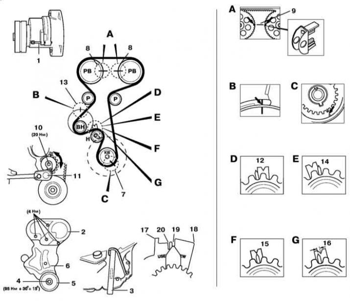
CV — Crankshaft
RV — Camshaft
VN - Water pump
R — Roller
H - Tensioner
Timing Belt Replacement on 2.0L DOHC Engines
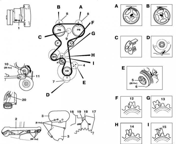
KV — Crankshaft
RV — Camshaft
VN - Water pump
R — Roller
H - Tensioner
Removal
Engines 1.4, 1.6 and 1.8 l DOHC
See illustration Replacing the timing belt on 1.4, 1.6 and 1.8 L DOHC engines.
1. Disconnect the negative cable from the battery.
2. Remove the air cleaner.
3. Set the parking brake, jack up the front of the car and place it on supports. Remove the right front wheel.
4. Mark the direction of rotation of the accessory drive belt with chalk or paint. Loosen the belt by retracting the tensioner with a spanner. Insert a 4 mm diameter rod through the aligned holes in the tensioner and support bracket [1]. Remove it from the engine.
5. Remove the upper section of the timing belt cover [2].
6. Support the engine using the KM-6001 device and install the KM-909-B centering tool.
7. Remove the accessory drive belt tensioner.
8. Remove the right powertrain suspension support assembly with its bracket.
9. Insert the special tool KM-911 [3] into the transmission dome and block the flywheel from turning.
10. Remove the mounting bolt [4] and remove the crankshaft pulley [5].
11. Remove the lower section of the timing belt cover [6].
12. Remove the flywheel locking tool.
13. If equipped, remove the camshaft position (CMP) sensor.
14. Temporarily screw the crankshaft pulley bolt back into place and, turning the crankshaft clockwise, bring the engine to the TDC position of the end of the compression stroke of the piston of the first cylinder (see Bringing the piston of the first cylinder to the position of the top dead center of the end of the compression stroke (TDC). Make sure that the alignment marks [7] are correctly aligned.
15. Check the correct alignment of the timing marks on the camshaft gears relative to the upper edge of the cylinder head [8].
16. Lock the camshaft gears using the special tool KM-852 [9].
17. Loosen the tensioner bolt [10] and using the Allen key [11] turn the latter clockwise until the left stop is in the appropriate position [12] - Type 1 or [17] - Type 2.
18. Tighten the tensioner bolt slightly.
19. Remove the timing belt.
Engines 2.0L DOHC
See illustration Timing Belt Replacement on 2.0L DOHC Engines.
1. Disconnect the negative cable from the battery.
2. Remove the air cleaner.
3. Set the parking brake, jack up the front of the car and place it on supports. Remove the right front wheel.
4. Mark the direction of rotation of the accessory drive belt with chalk or paint. Loosen the belt by retracting the tensioner with a spanner. Insert a 4 mm diameter rod through the aligned holes in the tensioner and support bracket [1]. Remove it from the engine.
5. Remove the upper section of the timing belt cover [3].
6. Support the engine using the KM-6001 device and install the KM-909-B centering tool.
7. Remove the accessory drive belt tensioner.
8. Remove the right powertrain suspension support assembly with its bracket.
9. Turn the crankshaft clockwise until the timing marks [4] are aligned.
10. Remove the mounting bolts [5] and remove the crankshaft pulley [6].
11. Make sure that the crankshaft timing marks are correctly aligned [7].
12. The timing marks on the camshaft gears must align with the corresponding marks on the rear timing drive cover [8].
13. Lock the camshaft gears using the special tool KM-853.
14. Loosen the tensioner bolt [10] and using the Allen key [11] turn the latter clockwise until the left stop is in the appropriate position [12] - Type 1 or [16] - Type 2.
15. Tighten the tensioner bolt slightly.
16. Remove the timing belt.
Installation
Engines 1.4, 1.6 and 1.8 l DOHC
See illustration Replacing the timing belt on 1.4, 1.6 and 1.8 L DOHC engines.
1. Make sure that the mark on the water pump housing is correctly aligned with the corresponding mark on the cylinder block [13].
2. Make sure that the alignment marks [7] and [8] are correctly aligned.
3. Starting from the crankshaft gear and moving counterclockwise, install the timing belt. Make sure the belt is taut in the areas between adjacent wheels.
4. Loosen the tensioner bolt [10].
5. Using the wrench [11], turn the tensioner counterclockwise until the right stop indicator is in the appropriate position [14] - Type 1 or [18] - Type 2.
6. Tighten the tensioner bolt slightly.
7. Remove the gear locking tool [9].
8. Turn the crankshaft two full turns clockwise and make sure that the timing marks [7] and [8] are correctly aligned.
9. Using the special tool KM-852, lock the camshaft gears [9].
10. Loosen the tensioner bolt.
11. Turn the tensioner clockwise until the pointer is in the appropriate position [15] - Type 1, new belt, [16] - Type 1, used belt, [19] - Type 2, new belt, [20] - Type 2, used belt.
12. Tighten the tensioner bolt slightly.
13. Remove the gear locking tool and slowly rotate the crankshaft two full turns clockwise, making sure that the timing marks [6] and [7] are correctly aligned.
14. Check that the tensioner indicator is correctly aligned (see item 11). If necessary, repeat the belt tension adjustment procedure.
15. Tighten the tensioner bolt to the required torque (20 Nm).
16. Insert the special tool KM-911 into the transmission dome and use it to block the flywheel from turning [3].
17. Remove the crankshaft pulley mounting bolt.
18. Proceeding in the reverse order of dismantling, install the removed components in their places.
Make sure that the original direction of rotation of the accessory drive belt is observed if it has not been replaced.
19. Install the new crankshaft pulley bolt and tighten it to the specified torque.
20. Remove the gear locking tool.
Engines 2.0L DOHC
See illustration Timing Belt Replacement on 2.0L DOHC Engines.
Make sure that the protrusion on the water pump housing is correctly aligned with the mating protrusion on the cylinder block [20].
1. Make sure that the alignment marks [7] and [8] are correctly aligned.
If you removed the camshaft gears, make sure the guide bushings are positioned correctly.
2. Starting from the crankshaft gear and moving counterclockwise, install the timing belt. Make sure the belt is taut in the areas between adjacent wheels.
3. Loosen the tensioner bolt [10].
4. Using the wrench [11], turn the tensioner counterclockwise until the right stop indicator is in the appropriate position [13] - Type 1 or [17] - Type 2.
5. Tighten the tensioner bolt slightly.
6. Remove the gear locking tool [9].
7. Turn the crankshaft two full turns clockwise and make sure that the timing marks [7] and [8] are correctly aligned.
8. Using the special tool KM-853, lock the camshaft gears [9] (refer to illustration 41.39).
9. Loosen the tensioner bolt.
10. Turn the tensioner clockwise until the pointer is in the appropriate position [14] - Type 1, new belt, [15] - Type 1, used belt, [18] - Type 2, new belt, [19] - Type 2, used belt.
11. Tighten the tensioner bolt to the required torque (20 Nm).
12. Remove the locking tool [9].
13. Turn the crankshaft two full turns clockwise and make sure that the timing marks [7] and [8] are correctly aligned.
14. Check the alignment of the tensioner indicator (see paragraph 65). If necessary, repeat the belt tension adjustment procedure.
15. Proceeding in the reverse order of dismantling, install the removed components in their places.
Make sure that the original direction of rotation of the accessory drive belt is observed if it has not been replaced.
16. Tighten the crankshaft pulley mounting bolts to the required torque (20 Nm).
Visitor comments