


General parameters
Full list of engines used to equip Opel Astra-G/ Zafira models
Petrol engines
Astra-G
|
Working volume (l) |
Code designation
|
Type
|
Developed power
|
Year of issue |
|
1.2 |
X12XE
|
1.2i 16V DOHC
|
kW (hp)
|
03/1988- |
|
Z12XE
|
1.2i 16V DOHC
|
48 (65)
|
sep.00 | |
|
1.4 |
X14XE
|
1.4i 16V DOHC
|
55 (75)
|
03/1998- |
|
Z14XE
|
1.4i 16V DOHC
|
66 (89)
|
09/2000- | |
|
1.6 |
X16SZR
|
1.6i SOHC
|
66 (89)
|
03/1998-08/2000 |
|
X16XEL
|
1.6i 16V DOHC
|
55 (75)
|
03/1998-08/2000 | |
|
C16SEL
|
1.6i SOHC
|
74 (100)
|
09/1998- | |
|
C16SEL
|
1.6i CS, CD,
|
74 (100)
|
10/1999- | |
|
Z16SE
|
1.6i SOHC
|
74 (100)
|
09/2000- | |
|
Z16XE
|
1.6i 16V DOHC
|
62 (85)
|
| |
|
Z16XE
|
Cabrio 1.6i 1 DOHC
|
74 (100)
|
03/2001- | |
|
1.8
|
X18XE1
|
1.8i 16V DOHC
|
74 (100)
|
03/1998-08/2000 |
|
X18XE1
|
Coupe 1.8i 16V DOHC
|
85 (115)
|
09/1999-08/2000 | |
|
X18XE1
|
1.8i CDE,
|
85 (115)
|
oct.99 | |
|
Z18XE
|
Coupe 1.8i 16V DOHC
|
85 (115)
|
09/2000- | |
|
Z18XE
|
1.8i 16V DOHC
|
92 (125)
|
09/2000- | |
|
Z18XEL
|
Coupe 1.8i DOHC
|
92 (125)
|
03/2001- | |
|
Z18XE
|
Cabrio 1.8i 1 DOHC
|
85 (115)
|
03/2001- | |
|
2.0
|
X20XEV
|
2.0i 16V DOHC
|
92 (125)
|
03/1988- |
|
C20SEL
|
2.0i CDX, CSX DOHC
|
100 (136)
|
10/1999- | |
|
Z20XER
|
2.0i 16V DOHC
|
95 (129)
|
09/2000- | |
|
Z20LET
|
Coupe 2.0i 16V DOHC
|
118 (160)
|
12/2000- | |
|
2.2
|
Z22SE
|
2.2i 16V DOHC
|
141 (192)
|
09/2000- |
|
Z22SE
|
Coupe 2.2i 16V DOHC
|
108 (147)
|
12/2000- | |
|
Z22SE
|
Cabrio 2.2i 1 DOHC
|
108 (147)
|
03/2001- |
Zafira
|
Working volume (l) |
Code designation
|
Type
|
Developed power
|
Year of issue |
|
1.6 |
X16XEL
|
1.6i 16V DOHC
|
74 (100)
|
03/1999-08/2000 |
|
Z16XEL
|
1.6i 16V DOHC
|
74 (100)
|
09/2000- | |
|
CNG (Gasmotor)
|
1.6i 16V
|
71 (96)
|
09/2001- | |
|
1.8
|
X18XE1
|
1.8i 16V DOHC
|
85 (115)
|
03/1999-08/2000 |
|
Z18XE
|
1.8i 16V DOHC
|
92 (125)
|
09/2000- | |
|
2.0 |
Z20
|
2.0 16V Turbo
|
141 (192)
|
09/2001- |
|
2.1 |
Z22SE
|
2.2 16V DOHC
|
108 (147)
|
09/2000- |
Diesel engines
Astra-G
|
Working volume (l) |
Code designation
|
Type
|
Developed power
|
Year of issue |
|
1.7 |
X17DTL
|
1.7DTL SOHC-Turbo
|
50 (75)
|
03/1998-08/2000 |
|
Y17DT
|
1.7DT DOHC
|
55 (75)
|
09/2000- | |
|
Y17DIT
|
1.7DIT DOHC-Turbo
|
55 (75)
|
08/2000- | |
|
2.0 |
X20DTL
|
2.0DTL 16V SOHC-Turbo
|
60 (82)
|
03/1998-08/2000 |
|
Y20DTL
|
2.0DTL 16V SOHC-Turbo
|
60 (82)
|
09/2000- | |
|
Y20DTH
|
2.0DTH 16V SOHC-Turbo
|
74 (100)
|
09/2000- | |
|
2.2 |
Y2.2DTR
|
2.2DTR
|
-
|
- |
Zafira
|
Working volume (l) |
Code designation
|
Type
|
Developed power
|
Year of issue |
|
2.0 |
X20DTL
|
2.0DTL 16V SOHC-Turbo
|
60 (82)
|
03/1998-08/2000 |
|
Y20DTL
|
2.0DTL 16V SOHC-Turbo
|
74 (100)
|
09/2000- | |
| 2.2 |
Y2.2DTR
|
2.2DTR
|
-
|
- |
Designations of engines covered in this Manual
Petrol engines
|
1.6L 8-valve SOHC engine |
X16SZR |
|
16-valve DOHC engines |
|
|
X14XE |
|
X16XEL |
|
X18XE1 |
|
X20XEV |
Diesel engines
|
1.7L SOHC 8-valve engine with low-pressure turbocharged |
X17DTL |
|
1.7L 16-valve DOHC non-turbo engine |
Y17DT |
|
2.0L 16-valve DOHC low-pressure turbocharged engine |
X20DTL/Y20DTL |
|
2.0L 16-valve DOHC high-pressure turbocharged engine
|
Y20DTH |
Main performance characteristics
Working volume of cylinders, cm³
|
Petrol engines |
|
|
1.2 l
|
1199 |
|
1.4 l
|
1389 |
|
1.6 l
|
1598 |
|
1.8 l
|
1796 |
|
2.0 l
|
1998 |
|
2.2 l
|
2198 |
|
Diesel engines |
|
|
1.7 l
|
1686 |
|
2.0 l
|
1995 |
|
2.2 l
|
2172 |
Engine power, kW (at rpm)/Torque, Nm (at rpm)
|
X12XE
|
48(5600)/110(4000) |
|
Z12XE
|
55(5600)/110(4000) |
|
Z14XE/X14XE
|
66(6000)/125(4000) |
|
Z16SE/X16SE
|
62(5400)/138(2600) |
|
Z16XE/X16XE
|
74(6000)/150(3600) |
|
Z16XEP/X16XEP
|
76(6000)/147(3600) |
|
Z18XE/X18XE
|
92(5600)/170(3800) |
|
Z20LET/X20LET
|
141(5400)/250(1950—5300) |
|
X20XEV
|
100(5600)/188(3400) |
|
X20XER
|
118(6800)/188(4300) |
|
Z22SE/X22SE
|
108(5800)/203(4000) |
|
Y17DT/X17DT
|
55(4400)/165(1800—3000) |
|
Y17DT (ECO)
|
55(4400)/165(1800—3000) |
|
X20DTL/Y20DTL
|
60(4300)/185(1800—2750) |
|
Y20DTH
|
74(4300)/230(1950—2500) |
|
Y22DTR
|
92(4000)/280(1500—2750) |
Compression ratio
|
Z12XE/X12XE
|
10.1:1 |
|
Z14XE/X14XE
|
10.5:1 |
|
X16SZR
|
9.6:1 |
|
Z16SE/X16SE
|
9.6:1 |
|
Z16XE/X16XE
|
10.5:1 |
|
Z16XEP/X16XEP
|
10.5:1 |
|
Z18XE/X18XE
|
10.5:1 |
|
Z20LET/X20LET
|
8.8:1 |
|
X20XEV
|
10.8:1 |
|
X20XER
|
10.8:1 |
|
Z22SE/X22SE
|
10.0:1 |
|
Y17DT/X17DT
|
18.4:1 |
|
Y17DT (ECO)
|
18.4:1 |
|
X20DTL/Y20DTL
|
18.5:1 |
|
Y20DTH
|
18.5:1 |
|
Y22DTR
|
18.5:1 |
Compression pressure
The data is provided only for the engines discussed in this Manual.
|
Petrol engines |
|
|
Nominal value (all considered in the Guide
engines), bar
|
12—15 |
|
Maximum permissible difference between cylinders (all considered
in the Engine Manual), bar
|
1 |
|
Diesel engines |
|
|
Nominal value, bar | |
|
12—15 |
|
26—30 |
|
25—28 |
|
Maximum permissible difference between cylinders, bar
| |
|
1 |
|
1 |
|
1 |
Maximum allowable rotation speed, rpm
|
Z12XE/X12XE
|
6250 |
|
Z14XE/X14XE
|
6400 |
|
Z16SE/X16SE
|
6000 |
|
Z16XE/X16XE
|
6400 |
|
Z16XEP/X16XEP
|
6400 |
|
Z18XE/X18XE
|
6400 |
|
Z20LET/X20LET
|
6400 |
|
X20XEV
|
Data not provided |
|
X20XER
|
Data not provided |
|
Z22SE/X22SE
|
6500 |
|
Y17DT/X17DT
|
5100—5300 |
|
Y17DT (ECO)
|
5200 |
|
X20DTL/Y20DTL
|
4750 |
|
Y20DTH
|
4950—5050 |
|
Y22DTR
|
4920—5080 |
Arrangement/number of cylinders/number of valves per cylinder
|
SOHC engines |
in-line/4/2 |
|
DOHC engines |
in-line/4/4 |
Cylinder firing order
1-3-4-2 (the first cylinder is located on the timing drive side)
Normal direction of rotation of the crankshaft
Clockwise
Cylinder diameter, mm
|
Z12XE/X12XE
|
72.5 |
|
Z14XE/X14XE
|
77.6 |
|
Z16SE/X16SE
|
79.0 |
|
Z16XE/X16XE
|
79.0 |
|
Z16XEP/X16XEP
|
79.0 |
|
Z18XE/X18XE
|
80.5 |
|
Z20LET/X20LET
|
86.0 |
|
X20XEV
|
86.0 |
|
X20XER
|
86.0 |
|
Z22SE/X22SE
|
86.0 |
|
Y17DT/X17DT
|
79.0 |
|
Y17DT (ECO)
|
79.0 |
|
X20DTL/Y20DTL
|
84.0 |
|
Y20DTH
|
84.0 |
|
Y22DTR
|
84.0 |
Piston stroke, mm
|
Z12XE/X12XE
|
72.6 |
|
Z14XE/X14XE
|
73.4 |
|
Z16SE/X16SE
|
81.5 |
|
Z16XE/X16XE
|
81.5 |
|
Z16XEP/X16XEP
|
81.5 |
|
Z18XE/X18XE
|
88.5 |
|
Z20LET/X20LET
|
86.0 |
|
X20XEV
|
86.0 |
|
X20XER
|
86.0 |
|
Z22SE/X22SE
|
94.5 |
|
Y17DT/X17DT
|
86.0 |
|
Y17DT (ECO)
|
86.0 |
|
X20DTL/Y20DTL
|
90.0 |
|
Y20DTH
|
90.0 |
|
Y22DTR
|
98.0 |
Operating parameters of engines
Operating parameters are given only for the engines discussed in this Manual (see above).
Dimensional characteristics of valve installation
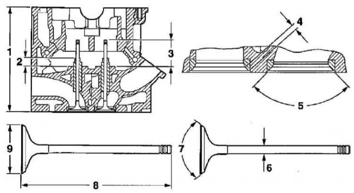
1 — Cylinder head height
2 — Valve guide bushing installation height
3 — Valve installation height
4 — Width of the working chamfer of the valve seat in the cylinder head
5 — Valve seat chamfer angle
6 — Valve stem diameter
7 — Valve plate chamfer angle
8 — Valve length
9 — Valve plate diameter
Cylinder head
Maximum permissible non-flatness of the mating surface, mm
|
Petrol engines |
0.05 |
|
Diesel engines |
|
|
Engines 1.7 l SOHC and DOHC |
0.1 |
|
2.0L Engines |
Data not provided |
Cylinder head height, mm
|
Petrol engines |
|
|
Engine 1.6L SOHC
|
95.9—96.1 |
|
Engines 1.4, 1.6 l DOHC
|
134.9—135.1 |
|
Engine 1.8L DOHC
|
135.8—36.0 |
|
Engine 2.0L DOHC
|
134 |
|
Diesel engines |
|
|
Engine 1.7L SOHC | |
|
106.10 |
|
105.75 |
|
Engines 1.7L DOHC |
94.95—95.05 |
|
2.0L Engines |
140.0 |
Width of working chamfers of valve seats, mm
|
Petrol engines |
|
|
Engine 1.6L SOHC | |
|
1.3—1.5 |
|
1.6—1.8 |
|
Engines 1.4, 1.6, 1.8 and 2.0 l DOHC | |
|
1.0—1.4 |
|
1.4—1.8 |
|
Diesel engines |
|
|
Engine 1.7 SOHC (inlet and outlet) | |
|
1.3 |
|
2.0 |
|
Engines 1.7L DOHC (inlet and outlet) |
1.5—1.7 |
|
2.0L Engines (inlet and outlet) |
1.4—1.8 |
Valve seat chamfer angle
|
Diesel engines 1.7L DOHC |
90° |
Camshaft
Axial clearance, mm
|
Petrol engines |
|
|
Engine 1.6L SOHC
|
0.09—0.21 |
|
Engines 1.4, 1.6, 1.8 and 2.0 l DOHC
|
0.04—0.015 |
|
Diesel engines |
|
|
Engine 1.7L SOHC
|
0.05—0.20 |
|
Engine 1.7L DOHC
|
Data not provided |
|
2.0L Engines
|
0.04—0.14 |
Maximum permissible value of radial runout, mm
|
Petrol engines |
0.040 |
|
Diesel engines |
|
|
Engines 1.7 l SOHC and DOHC |
0.05 |
|
2.0L Engines |
0.06 |
Height of cam lift, mm
|
Petrol engines |
|
|
Engine 1.6L SOHC | |
|
5.61 |
|
6.12 |
|
Engines 1.4, 1.6,1.8 DOHC | |
|
8.5 |
|
8.0 |
|
2.0L DOHC | |
|
10.0 |
|
10.0 |
|
Diesel engines |
|
|
Engine 1.7L SOHC | |
|
9.40 |
|
9.40 |
|
Engine 1.7L DOHC | |
|
7.68 |
|
7.77 |
|
2.0L Engines | |
|
8.0 |
|
8.0 |
The size of the clearances in the support bearings
Data not provided
Valves and guide bushings
Height of protrusion of guide bushings above head surface, mm
|
Petrol engines |
|
|
Engine 1.6L SOHC |
80.85—81.25 |
|
Engines 1.4, 1.6 and 1.8 l DOHC |
10.70—11.00 |
|
Engine 2.0L DOHC |
13.7—14.0 |
|
Diesel engines |
|
|
2.0L Engines |
11.20—11.50 |
Valve stem diameter, mm
|
Petrol engines |
|
|
Engine 1.6L SOHC | |
|
Standard size (identification mark K) | |
|
6.998—7.012 |
|
6.978—6.992 |
|
Repair size 0.075 mm (identification mark K1)
| |
|
7.073—7.087 |
|
7.053—7.067 |
|
Repair size 0.150 mm (identification tag K2)
| |
|
7.148—7.162 |
|
7.128—7.142 |
|
Engines 1.4 and 1.6 l DOHC | |
|
Standard size (gM identification tag) | |
|
5.995—5.970 |
|
5.935—5.950 |
|
Repair size 0.075 mm (identification mark K1)
| |
|
6.030—6.045 |
|
6.010—6.025 |
|
Repair size 0.150 mm (identification tag K2)
| |
|
6.105—6.120 |
|
6.085—6.100 |
|
Engines 1.8L DOHC | |
|
Standard size (gM identification tag) | |
|
4.955—4.970 |
|
4.935—4.950 |
|
Engine 2.0L DOHC | |
|
Standard size (gM identification tag) | |
|
5.955—5.970 |
|
5.945—5.960 |
|
Repair size 0.075 mm (identification mark K1)
| |
|
6.030—6.045 |
|
6.020—6.035 |
|
Repair size 0.150 mm (identification tag K2)
| |
|
6.105—6.120 |
|
6.095—6.110 |
|
Diesel engines |
|
|
Engines 1.7L DOHC | |
|
Standard size | |
|
7.970—7.985 |
|
7.955—7.970 |
|
Repair size 0.075 mm | |
|
8.045—8.060 |
|
8.030—8.045 |
|
Repair size 0.150 mm | |
|
8.120—8.135 |
|
8.105—8.120 |
|
Engines 1.7L DOHC | |
|
6.00 |
|
6.00 |
|
2.0L Engines | |
|
Standard size (identification mark K) | |
|
5.955—5.970 |
|
5.945—5.960 |
|
Repair size 0.075 mm (identification mark K1)
| |
|
6.030—6.045 |
|
6.020—6.035 |
|
Repair size 0.150 mm (identification tag K2)
| |
|
6.105—6.120 |
|
6.095—6.110 |
Maximum permissible valve runout, mm
|
All engines |
0.03 |
Inner diameter of guide bushings, mm
|
Petrol engines |
|
|
Engine 1.6L SOHC | |
|
7.030—7.050 |
|
7.105—7.125 |
|
7.180—7.200 |
|
Engines 1.4 and 1.6 l DOHC | |
|
6.000—6.012 |
|
6.075—6.090 |
|
6.150—6.165 |
|
Engines 1.8L DOHC | |
|
5.000—5.012 |
|
5.075—5.087 |
|
5.150—5.162 |
|
Engine 2.0L DOHC | |
|
6.000—6.012 |
|
6.075—6.090 |
|
6.150—6.165 |
|
Diesel engines |
|
|
Engines 1.7L DOHC | |
|
8.000—8.017 |
|
8.075—8.092 |
|
8.150—8.167 |
|
Engines 1.7L DOHC |
7.000—7.015 |
|
2.0L Engines | |
|
6.000—6.012 |
|
6.075—6.090 |
|
6.150—6.165 |
Valve stem seat clearance in guide bushing, mm
|
Petrol engines |
|
|
Engine 1.6L SOHC | |
|
0.018—0.052 |
|
0.038—0.072 |
|
Engines 1.4, 1.6 and 1.8 l DOHC |
Data not provided |
|
Engine 2.0L DOHC | |
|
0.030—0.057 |
|
0.040—0.067 |
|
Diesel engines |
|
|
Engine 1.7L SOHC | |
|
Nominal value | |
|
0.015 |
|
0.030 |
|
Maximum permissible value | |
|
0.047 |
|
0.062 |
|
Engines 1.7L DOHC | |
|
Nominal value | |
|
0.019 |
|
0.0215 |
|
Maximum permissible value
|
Data not provided |
|
2.0L Engines |
Data not provided |
Valve length, mm
|
Petrol engines |
|
|
Engine 1.6L SOHC | |
|
99.35 |
|
99.65 |
|
Engines 1.4 and 1.6 l DOHC | |
|
101.51—101.93 |
|
100.55—100.97 |
|
Engine 1.8L DOHC | |
|
100.1—100.3 |
|
99.4—99.6 |
|
Engine 2.0L DOHC | |
|
102.0—102.2 |
|
92.15—92.35 |
|
Diesel engines |
|
|
Engine 1.7L SOHC |
123.22—123.27 |
|
Engines 1.7L DOHC | |
|
98.45 |
|
98.10 |
|
2.0L Engines | |
|
97.1—97.2 |
|
96.9—97.0 |
Height of installed valves, mm
|
1.6L SOHC petrol engine |
13.75—14.35 |
Valve plate diameter, mm
|
Petrol engines |
|
|
Engine 1.6L SOHC | |
|
38.0 |
|
31.0 |
|
Engines 1.4 and 1.6 l DOHC | |
|
31.0 |
|
27.5 |
|
Engine 1.8L DOHC | |
|
31.2 |
|
27.5 |
|
Engine 2.0L DOHC | |
|
31.9—32.1 |
|
28.9—29.1 |
|
Diesel engines |
|
|
Engine 1.7L SOHC | |
|
36.0 |
|
32.0 |
|
Engines 1.7L DOHC | |
|
27.15 |
|
28.5 |
|
2.0L Engines | |
|
28.9—29.1 |
|
25.9—26.1 |
Angle of inclination of working chamfers of valve plates
|
Diesel engines 1.7L DOHC |
89° |
Valve guide bush length, mm
|
Diesel engines 1.7L DOHC |
41.75—42.25 |
Valve clearances on a cold engine (only diesel engine 1.7L DOHC), mm
|
Intake valves |
0.4 ±0.5 |
|
Exhaust valves |
0.4 ±0.5 |
Balancing assembly (2.0 DOHC petrol engine when equipped accordingly)
Gap size, mm
|
0.02—0.6 |
The ratio of the plate code to its thickness
|
Code 55
|
0.535—0.565 |
|
Code 58
|
0.565—0.595 |
|
Code 61
|
0.595—0.625 |
|
Code 64
|
0.625—0.655 |
|
Code 67
|
0.655—0.685 |
|
Code 70
|
0.685—0.715 |
|
Code 73
|
0.715—0.745 |
|
Code 76
|
0.745—0.775 |
|
Code 79
|
0.775—0.805 |
|
Code 82
|
0.805—0.835 |
|
Code 85
|
0.835—0.865 |
Cylinder block
Maximum permissible non-flatness of the mating surface, mm
|
Petrol engines |
0.05 |
|
Diesel engines |
|
|
Engines 1.7 l SOHC and DOHC |
0.1 |
|
2.0L Engines |
Data not provided |
Cylinder diameter, mm
|
Petrol engines |
|
|
Engines 1.6L SOHC | |
|
Standard size | |
|
78.975—78.985 |
|
78.985—78.995 |
|
78.995—79.005 |
|
79.005—79.015 |
|
79.015—79.025 |
|
Repair size 0.5 mm (Group 7)
|
79.465—79.475 |
|
Engines 1.4L DOHC | |
|
Standard size | |
|
77.575—77.585 |
|
77.585—77.595 |
|
77.595—77.605 |
|
77.605—77.615 |
|
77.615—77.625 |
|
Repair size 0.5 mm (Group 7)
|
78.065—78.075 |
|
Engines 1.6L DOHC | |
|
Standard size | |
|
78.975—78.985 |
|
78.985—78.995 |
|
78.995—79.005 |
|
79.005—79.015 |
|
79.015—79.025 |
|
Repair size 0.5 mm (Group 7)
|
79.465—79.475 |
|
Engines 1.8L DOHC | |
|
Standard size | |
|
80.485—80.495 |
|
80.495—80.505 |
|
80.505—80.515 |
|
80.515—80.525 |
|
Repair size 0.5 mm (Group 00)
|
80.995—81.005 |
|
Engine 2.0L DOHC | |
|
Standard size | |
|
85.975—78.985 |
|
85.985—85.995 |
|
85.995—86.005 |
|
86.005—86.015 |
|
86.015—86.025 |
|
Repair size 0.5 mm (Group 7)
|
86.465—86.475 |
|
Diesel engines |
|
|
Engine 1.7L SOHC | |
|
Standard size | |
|
82.475—82.485 |
|
82.485—82.495 |
|
82.495—82.505 |
|
82.505—82.515 |
|
82.515—82.525 |
|
Repair size 0.5 mm (Group 7)
|
82.965—82.975 |
|
Engines 1.7L DOHC | |
|
79.000—79.009 |
|
79.010—79.019 |
|
79.020—79.029 |
|
2.0L Engines | |
|
Standard size | |
|
83.975—83.985 |
|
83.985—83.995 |
|
83.995—84.005 |
|
84.005—84.015 |
|
84.015—84.025 |
|
Repair size 0.5 mm
|
84.465—84.475 |
Inner diameter of main bearing beds without liners (1.7L DOHC diesel engines only), mm
|
Group 1 |
55.992—56.000 |
|
Group 2 |
55.984—55.992 |
|
Group 3 |
55.976—55.984 |
Maximum permissible ovality of cylinders, mm
|
Petrol engines |
0.013 |
Maximum permissible taper of cylinders, mm
|
Petrol engines |
0.013 |
|
Diesel engines |
|
|
Engines 1.7 l SOHC and DOHC |
0.015 |
|
2.0L Engines |
Data not provided |
Connecting rod and piston assemblies
Pistons and piston rings
Piston diameter, mm
|
Petrol engines |
|
|
Engines 1.6L SOHC | |
|
Standard size | |
|
78.955—78.965 |
|
78.965—78.975 |
|
78.975—78.985 |
|
78.985—78.995 |
|
78.995—79.005 |
|
Repair size 0.5 mm (Group 7)
|
79.445—79.455 |
|
Engines 1.4L DOHC | |
|
Standard size | |
|
77.555—77.565 |
|
77.565—77.575 |
|
77.575—77.585 |
|
77.585—77.595 |
|
77.595—77.605 |
|
Repair size 0.5 mm (Group 7)
|
78.045—78.055 |
|
Engines 1.6L DOHC | |
|
Standard size | |
|
78.955—78.965 |
|
78.965—78.975 |
|
78.975—78.985 |
|
78.985—78.995 |
|
78.995—79.005 |
|
Repair size 0.5 mm (Group 7)
|
79.445—79.455 |
|
Engines 1.8L DOHC | |
|
Standard size | |
|
80.455—80.465 |
|
80.465—80.475 |
|
80.475—80.485 |
|
80.485—80.495 |
|
Repair size 0.5 mm (Group 00)
|
80.965—80.975 |
|
Engine 2.0L DOHC | |
|
Standard size | |
|
85.945—78.955 |
|
85.955—85.965 |
|
85.965—85.975 |
|
85.975—85.985 |
|
85.985—85.995 |
|
Repair size 0.5 mm (Group 7)
|
86.435—86.445 |
|
Diesel engines |
|
|
Engine 1.7L SOHC | |
|
Standard size | |
|
82.445—82.455 |
|
82.455—82.465 |
|
82.465—82.475 |
|
82.475—82.485 |
|
82.485—82.495 |
|
Repair size 0.5 mm (Group 7)
|
82.935—82.945 |
|
Engines 1.7L DOHC | |
|
78.930—78.939 |
|
78.940—78.949 |
|
78.950—78.959 |
|
2.0L Engines | |
|
Engine X20DTL/Y20DTL | |
| |
|
83.905—83.915 |
|
83.915—83.925 |
|
83.925—83.935 |
|
83.935—83.945 |
|
83.945—83.955 |
|
84.395—84.405 |
|
X20DTH Engine | |
| |
|
83.885—83.915 |
|
83.895—83.905 |
|
83.905—83.915 |
|
83.915—83.925 |
|
83.925—83.935 |
|
84.375—84.385 |
Piston clearance in cylinder, mm
|
Petrol engines |
0.02—0.04 |
|
Diesel engines |
|
|
Engine 1.7L SOHC |
0.02—0.04 |
|
Engine 1.7L DOHC |
0.061—0.08 |
|
2.0L Engines |
|
|
0.06—0.08 |
|
0.08—0.10 |
Piston protrusion value (diesel engines 1.7 l), mm
|
SOHC Engine |
0.65—0.095 |
|
DOHC Engine |
0.063—0.083 |
Clearances in piston ring locks, mm
|
Petrol engines |
|
|
0.3—0.5 |
|
0.4—1.4 |
|
Diesel engines |
|
|
Engine 1.7L SOHC | |
|
0.20—0.40 |
|
0.25—0.50 |
|
Engine 1.7L DOHC | |
|
0.25—0.35 |
|
0.20—0.30 |
|
0.20—0.40 |
|
2.0L Engines | |
|
0.25—0.50 |
|
0.25—0.50 |
Piston ring thickness, mm
|
Petrol engines |
|
|
Engine 1.6L SOHC | |
|
1.2 |
|
1.5 |
|
3.0 |
|
Engine 1.4L DOHC | |
|
1.2 |
|
1.5 |
|
3.0 |
|
1.6 and 2.0 L DOHC engines | |
|
1.5 |
|
1.5 |
|
3.0 |
|
Engine 1.8L DOHC | |
|
1.2 |
|
1.2 |
|
2.0 |
|
Diesel engines |
|
|
Engine 1.7L SOHC | |
|
2.0 |
|
3.0 |
|
Engine 1.7L DOHC | |
|
2.0 |
|
1.5 |
|
3.0 |
|
2.0L Engines | |
| |
|
2.0 |
|
2.5 |
|
1.75 |
|
3.0 |
The value of the lateral clearance of the ring seat in the piston groove, mm
|
Petrol engines |
|
|
Engine 1.6L SOHC and 1.4, 1.6 and 1.8L DOHC
| |
|
0.02—0.04 |
|
0.04—0.06 |
|
0.01—0.03 |
|
Engine 2.0 DOHC | |
|
0.02—0.04 |
|
0.01—0.03 |
|
Diesel engines |
|
|
Engine 1.7L SOHC | |
|
0.12—0.18 |
|
0.12—0.15 |
|
0.025—0.15 |
|
Engine 1.7L DOHC | |
|
0.09—0.15 |
|
0.04—0.15 |
|
0.02—0.15 |
|
2.0L Engines | |
|
Engine X20DTL/Y20DTL | |
|
0.11—0.16 |
|
0.05—0.09 |
|
0.03—0.07 |
|
Y20DTH Engine | |
|
0.08—0.12 |
|
0.05—0.09 |
|
0.03—0.07 |
Piston pins
Diameter, mm
|
Petrol engines |
|
|
Engines 1.6L SOHC and 1.4, 1.6 and 1.8L DOHC |
17.997—18.000 |
|
Engine 2.0L DOHC |
21.000 |
|
Diesel engines |
|
|
Engine 1.7L SOHC |
26 |
|
Engine 1.7L DOHC |
27 |
|
2.0L Engines |
29 |
Length, mm
|
Petrol engines |
|
|
Engines 1.6L SOHC and 1.4, 1.6 and 1.8L DOHC |
55 |
|
Engine 2.0L DOHC |
55.7—58.0 |
|
Diesel engines |
|
|
Engine 1.7L SOHC |
69 |
|
Engine 1.7L DOHC |
64 |
|
2.0L Engines |
68 |
Clearance of the pin seat in the piston, mm
|
Petrol engines |
|
|
Engines 1.6L SOHC |
0.009—0.012 |
|
Engines 1.4, 1.6 and 1.8 l DOHC |
0.007—0.010 |
|
Engine 2.0L DOHC |
0.011—0.014 |
|
Diesel engines |
|
|
Engine 1.7L SOHC |
0.007—0.011 |
|
Engine 1.7L DOHC |
0.002—0.012 |
Clearance of the pin seat in the upper head of the connecting rod, mm
|
Diesel engines |
|
|
Engine 1.7L SOHC |
0.014—0.025 |
|
Engine 1.7L DOHC |
0.002—0.015 |
Connecting rods
Axial clearance value on crankshaft journal, mm
|
Petrol engines |
|
|
Engine 1.6L SOHC |
0.07—0.24 |
|
Engines 1.4, 1.6 and 1.8 l DOHC |
0.11—0.24 |
|
Engine 2.0L DOHC |
0.07—0.24 |
|
Diesel engines |
|
|
Engine 1.7L SOHC |
0.20—0.40 |
|
Engine 1.7L DOHC |
0.25—0.58 |
|
2.0L Engines |
0.07—0.28 |
Maximum allowable difference in connecting rod weight (only diesel engines 1.7L SOHC and DOHC), G
|
4 |
Crankshaft
Axial clearance of the crankshaft, mm
|
Petrol engines |
|
|
Engines 1.6L SOHC and 1.4, 1.6 and 1.8L DOHC |
0.1—0.2 |
|
Engine 2.0L DOHC |
0.03—0.15 |
|
Diesel engines |
|
|
Engine 1.7L SOHC |
0.06—0.30 |
|
Engine 1.7L DOHC |
0.03—0.15 |
|
2.0L Engines |
0.05—0.15 |
Main journal diameter, mm
|
Petrol engines |
|
|
Engines 1.6L SOHC and 1.4, 1.6 and 1.8L DOHC | |
|
Standard size
|
54.980—54.997 |
|
First repair size (0.25 mm)
|
54.730—54.747 |
|
Second repair size (0.50 mm)
|
54.482—54.495 |
|
Engine 2.0L DOHC | |
|
Standard size | |
|
57.974—57.981 |
|
57.981—57.988 |
|
57.988—57.995 |
|
57.732—57.745 |
|
57.482—57.495 |
|
Diesel engines |
|
|
Engine 1.7L SOHC | |
|
Standard size
|
57.974—57.995 |
|
First repair size (0.25 mm)
|
57.732—57.738 |
|
Second repair size (0.50 mm)
|
57.482—57.495 |
|
Engine 1.7L DOHC | |
|
First size group (one cutout)
|
51.928—51.938 |
|
Second size group (two cutouts)
|
51.918—51.928 |
|
Engine 2.0 l | |
|
Standard size | |
|
67.966—67.974 |
|
67.974—67.982 |
|
67.716—67.732 |
|
67.466—67.482 |
Diameter of connecting rod journals, mm
|
Petrol engines |
|
|
Engines 1.6L SOHC and 1.4, 1.6 and 1.8L DOHC
| |
|
Standard size
|
42.971—42.987 |
|
First repair size (0.25 mm)
|
42.721—42.737 |
|
Second repair size (0.50 mm)
|
42.471—42.487 |
|
Engine 2.0L DOHC | |
|
Standard size
|
48.970—48.988 |
|
First repair size (0.25 mm)
|
48.720—48.738 |
|
Second repair size (0.50 mm)
|
48.470—48.488 |
|
Diesel engines |
|
|
Engine 1.7L SOHC | |
|
Standard size
|
48.970—48.988 |
|
First repair size
|
48.720—48.738 |
|
Second repair size (0.50 mm)
|
48.470—48.488 |
|
Engine 1.7L DOHC |
Data not provided |
|
Engine 2.0 l | |
|
Standard size
|
48.971—48.990 |
|
First repair size (0.25 mm)
|
48.721—48.740 |
|
Second repair size (0.50 mm)
|
48.471—48.490 |
Maximum permissible value of neck ovality, mm
|
Petrol engines |
0.04 |
|
Diesel engines |
|
|
Engines 1.7 l SOHC and DOHC |
Data not provided |
|
2.0L Engines |
0.03 |
Maximum permissible value of neck taper, mm
|
Petrol engines |
Data not provided |
|
Diesel engines |
Data not provided |
Maximum permissible value of shaft radial runout, mm
|
Petrol engines |
0.03 |
|
Diesel engines |
|
|
Engines 1.7L SOHC |
0.06 |
|
Engines 1.7L DOHC |
0.04—0.082 |
|
2.0L Engines |
0.03 |
Clearance size in main bearings, mm
|
Petrol engines |
|
|
Engines 1.6L SOHC and 1.4, 1.6 and 1.8L DOHC |
0.017—0.047 |
|
Engine 2.0L DOHC |
0.015—0.040 |
|
Diesel engines |
|
|
Engines 1.7L SOHC |
0.030—0.080 |
|
Engines 1.7L DOHC |
0.030—0.058 |
|
2.0L Engines |
0.016—0.069 |
Clearance size in connecting rod bearings, mm
|
Petrol engines |
|
|
Engines 1.6L SOHC and 1.4, 1.6 and 1.8L DOHC |
0.019—0.071 |
|
Engine 2.0L DOHC |
0.006—0.031 |
|
Diesel engines |
|
|
Engines 1.7L SOHC |
0.025—0.100 |
|
Engines 1.7L DOHC |
0.025—0.058 |
|
2.0L Engines |
0.022—0.061 |
Lubrication system
Oil pump type
|
Petrol engines |
|
|
Engines 1.6L SOHC |
Gear, with direct drive from the crankshaft shaft |
|
Engines 1.4, 1.6, 1.8 and 2.0 l DOHC |
Rotary, timing belt driven |
|
Diesel engines |
|
|
Engine 1.7L SOHC |
Rotary, direct drive from the crankshaft |
|
Engine 1.7L DOHC |
Rotary, timing belt driven |
|
2.0L Engines |
Gear, with direct drive from the crankshaft shaft |
Minimum allowable pressure at idle speed with engine temperature not lower than 80°C, bar
|
Petrol engines |
1.5 |
|
Diesel engines |
|
|
Engine 1.7L SOHC |
3.9 |
|
Engine 1.7L DOHC |
1.27 |
|
2.0L Engines |
1.5 |
The size of the working clearances in the oil pump, mm
|
Petrol engines |
|
|
Engines 1.6L SOHC | |
|
Gear tooth engagement gap
|
0.08—0.15 |
|
Axial clearance of gears
|
0.10—0.20 |
|
Engines 1.4, 1.6, 1.8 and 2.0 l DOHC | |
|
Gap between gear teeth
|
0.10—0.20 |
|
Axial clearance of gears
|
0.03—0.10 |
|
Diesel engines |
|
|
Engine 1.7L SOHC | |
|
Lateral clearance of outer rotor fit | |
|
0.24—0.36 |
|
0.40 |
|
Gap between rotor teeth | |
|
0.10 |
|
0.145 |
|
Axial play of rotors | |
|
0.035—0.100 |
|
0.150 |
|
Engine 1.7L DOHC | |
|
Lateral clearance of outer rotor fit | |
|
0.24—0.36 |
|
0.40 |
|
Gap between rotor teeth | |
|
0.13—0.15 |
|
0.20 |
|
Axial play of rotors | |
|
0.035—0.100 |
|
0.150 |
|
2.0L Engines |
Data not provided |
Tightening force of threaded connections, Nm
|
Connection type |
Meaning |
|
Wheel mounting bolts |
110 |
Petrol engines
Engine 1.6L SOHC
|
Connection type |
Meaning |
|
Timing Belt Cover Fastening Bolts | |
|
4 |
|
6 |
|
Timing Belt Tensioner Fixing Bolt
|
20 |
|
Timing mechanism cover mounting bolts
|
8 |
|
Camshaft timing gear bolt
|
45 |
|
Camshaft Rear Thrust Plate Bolts
|
8 |
|
Timing mechanism housing end cover bolts
|
8 |
|
Connecting rod lower head cap bolts * | |
|
25 |
|
extend to an angle of 30° |
|
Water pump mounting bolts
|
8 |
|
Crankshaft Pulley Bolt * | |
|
95 |
|
extend to an angle of 30° |
|
extend to an angle of 15° |
|
Crankshaft Position Sensor (CKP) Rotor Mounting Bolts
|
8 |
|
Cylinder head mounting bolts * | |
|
25 |
|
pull to an angle of 60° |
|
pull to an angle of 60° |
|
pull to an angle of 60° |
|
Drive Disc Mounting Bolts * | |
|
55 |
|
extend to an angle of 30° |
|
extend to an angle of 15° |
|
Drive Disc Cover Fastener
|
8 |
|
Powertrain suspension mounts | |
|
Left support | |
|
55 |
|
55 |
|
20 |
|
35 |
|
15 |
|
Front support | |
|
55 |
|
Rear support | |
|
55 |
|
55 |
|
60 |
|
Right support | |
|
55 |
|
35 |
|
Engine to transmission mounting bolts | |
|
60 |
|
Flywheel mounting bolts * | |
|
35 |
|
extend to an angle of 30° |
|
extend to an angle of 15° |
|
Front subframe mounting bolts * | |
|
90 |
|
pull to an angle of 45° |
|
extend to an angle of 15° |
|
Crankshaft main bearing cap fastening bolts shaft | |
|
50 |
|
pull to an angle of 45° |
|
extend to an angle of 15° |
|
Oil pressure alarm sensor
|
30 |
|
Oil pump | |
|
8 |
|
6 |
|
50 |
|
Oil intake mounting bolts
|
8 |
|
Engine oil pan mounting bolts | |
|
Models without K/V (stamped pallet) | |
|
10 |
|
55 |
|
Models with K/V (cast pallet) | |
|
10 |
|
40 |
|
45 |
* Use new bolts.
Engines 1.4, 1.6 and 1.8 l DOHC
|
Connection type |
Meaning |
|
Timing Belt Cover Bolts | |
|
3 |
|
6 |
|
Timing drive intermediate roller mounting bolt
|
25 |
|
Timing Belt Tensioner Fastening Bolt
|
20 |
|
Auxiliary drive belt tensioner mounting bolt
units to the generator bracket
|
35 |
|
Oil pan deflector plate bolts
|
8 |
|
Camshaft Bearing Cap Bolts
|
8 |
|
Timing mechanism housing cover bolts
|
8 |
|
Camshaft Position Sensor Mounting Bolts
shaft (CMP)
|
8 |
|
Camshaft timing gear mounting bolt * | |
|
50 |
|
pull to an angle of 60° |
|
extend to an angle of 15° |
|
Bolt for fastening the lower connecting rod head caps * | |
|
25 |
|
turn 30° |
|
Crankshaft Pulley Bolt * | |
|
95 |
|
extend to an angle of 30° |
|
extend to an angle of 15° |
|
Position sensor mounting bracket mounting bolt
crankshaft (CKP)
|
8 |
|
Cylinder head mounting bolts * | |
|
25 |
|
pull to a 90° angle |
|
pull to a 90° angle |
|
pull to a 90° angle |
|
pull to an angle of 45° |
|
Drive Disc Mounting Bolts
|
60 |
|
Powertrain suspension mounts | |
|
Left support | |
|
20 |
|
35 |
|
55 |
|
Front support | |
|
60 |
|
55 |
|
Rear support | |
|
55 |
|
55 |
|
55 |
|
Right support | |
|
50 |
|
45 |
|
55 |
|
55 |
|
Engine to transmission mounting bolts | |
|
60 |
|
Front subframe mounting bolts * | |
|
90 |
|
pull to an angle of 45° |
|
extend to an angle of 15° |
|
Flywheel mounting bolts * | |
|
35 |
|
extend to an angle of 30° |
|
extend to an angle of 15° |
|
Main Bearing Cap Bolts * | |
|
50 |
|
pull to an angle of 45° |
|
extend to an angle of 15° |
|
Engine oil level sensor mounting bolts with
tORX type head
|
8 |
|
Oil pump | |
|
8 |
|
6 |
|
50 |
|
30 |
|
Oil intake mounting bolts
|
8 |
|
Engine oil pan mounting bolts | |
|
10 |
|
40 |
|
|
|
10 |
|
45 |
* Use new bolts.
Engine 2.0L DOHC
|
Connection type |
Meaning |
|
Timing Belt Cover Bolts
|
6 |
|
Timing drive intermediate roller mounting bolt | |
|
25 |
|
25 |
|
Timing Belt Tensioner Fastening Bolt
|
20 |
|
Auxiliary drive belt tensioner mounting bolt units to the generator bracket | |
|
35 |
|
25 |
|
Bolts for fastening the balancing assembly to the cylinder block
| |
|
20 |
|
pull to an angle of 45° |
|
Oil pan deflector plate mounting bolts
|
8 |
|
Camshaft bearing cap mounting bolts
|
8 |
|
Timing mechanism cover mounting bolts
|
8 |
|
Camshaft Position (CMP) Sensor Mounting Bolts
|
6 |
|
Camshaft timing gear mounting bolt *
| |
|
50 |
|
pull to an angle of 60° |
|
extend to an angle of 15° |
|
Bolts for fastening the lower connecting rod head caps * | |
|
35 |
|
pull to an angle of 45° |
|
extend to an angle of 15° |
|
Central crankshaft pulley mounting bolt * | |
|
95 |
|
extend to an angle of 30° |
|
extend to an angle of 15° |
|
Crankshaft pulley mounting bolts
|
20 |
|
Crankshaft timing gear mounting bolt | |
|
130 |
|
extend to an angle of 50° |
|
Cylinder head mounting bolts * | |
|
25 |
|
pull to a 90° angle |
|
pull to a 90° angle |
|
pull to a 90° angle |
|
extend to an angle of 15° |
|
Drive Disc Mounting Bolts * | |
|
55 |
|
extend to an angle of 30° |
|
extend to an angle of 15° |
|
Powertrain suspension mounts | |
|
Left support | |
|
20 |
|
35 |
|
55 |
|
Front support | |
|
60 |
|
55 |
|
Rear support | |
|
55 |
|
55 |
|
55 |
|
Right support | |
|
50 |
|
45 |
|
55 |
|
55 |
|
Engine to transmission mounting bolts | |
|
60 |
|
Flywheel mounting bolts * | |
|
65 |
|
extend to an angle of 30° |
|
extend to an angle of 15° |
|
Bolts for fastening the main bearing cap bridge to the block cylinders | |
|
20 |
|
pull to an angle of 45° |
|
Main Bearing Cap Bolts * | |
|
50 |
|
pull to an angle of 45° |
|
extend to an angle of 15° |
|
Bridge cap bolts to main bearing caps
|
20 |
|
Oil level sensor mounting bolts (with TORX head)
|
8 |
|
Oil pump | |
|
8 |
|
6 |
|
50 |
|
Oil intake mounting bolts | |
|
8 |
|
20 |
|
Engine oil pan mounting bolts | |
|
Lower section pallet mounting bolts | |
|
8 |
|
Bolts for fastening the main (cast) section of the pallet | |
|
20 |
|
40 |
|
Drain plug
|
10 |
* Use new bolts/nuts.
Diesel engines
Engines 1.7L SOHC
|
Connection type |
Meaning |
|
Compressor support bracket mounting bolts K/V
|
40 |
|
Compressor fastener K/V
|
20 |
|
Generator Upper Support Bracket Fastener
|
18 |
|
Lower generator mounting bolt
|
25 |
|
Fastening the compressor bracket to the drive belt tensioner auxiliary units | |
|
8 |
|
Camshaft timing gear mounting bolt * | |
|
75 |
|
turn 60° |
|
Fastening the cooling system hose to the cylinder block
|
20 |
|
Water pump | |
|
25 |
|
10 |
|
Bolts for fastening the lower connecting rod head caps * | |
|
35 |
|
pull to an angle of 45° |
|
extend to an angle of 15° |
|
Crankshaft pulley mounting bolts
|
20 |
|
Crankshaft speed sensor mounting bolt
|
8 |
|
Crankshaft timing gear mounting bolt * | |
|
130 |
|
pull to an angle of 45° |
|
Cylinder head mounting bolts | |
|
25 |
|
pull to a 90° angle |
|
pull to a 90° angle |
|
pull to an angle of 45° |
|
after warming up the engine in 2 stages, tighten to angles of 30° 15° |
|
Powertrain suspension mounts | |
|
Left support | |
|
55 |
|
55 |
|
20 |
|
35 |
|
15 |
|
Front support | |
|
60 |
|
55 |
|
Rear support | |
|
55 |
|
55 |
|
80 |
|
Right support | |
|
55 |
|
55 |
|
35 |
|
50 |
|
Engine to transmission mounting bolts
|
60 |
|
Bolts for fastening the transport eyes of the power unit
|
25 |
|
Exhaust system inlet pipe mounting bolts
|
20 |
|
EGR valve to exhaust manifold mounting bolts
|
8 |
|
Exhaust manifold to cylinder head mounting nuts *
|
22 |
|
Exhaust manifold to cylinder head mounting bolts
|
22 |
|
Exhaust manifold support bracket fastener
|
25 |
|
Flywheel mounting bolts * | |
|
65 |
|
extend to an angle of 30° |
|
extend to an angle of 15° |
|
Fuel injection pump gear mounting bolts
|
15 |
|
Fuel injection pump connector bolts
|
25 |
|
Main bearing cap bridge mounting bolts | |
|
20 |
|
pull to an angle of 45° |
|
Main Bearing Cap Bolts * | |
|
50 |
|
pull to an angle of 45° |
|
extend to an angle of 15° |
|
Oil cooler support bracket mounting bolts
|
5 |
|
Oil cooler pipe nipple connection
|
30 |
|
Bolt for fastening the support bracket of the measuring probe guide tube
engine oil level to the block
|
25 |
|
Oil filter
|
15 |
|
Oil pressure reducing valve mounting bolts
|
50 |
|
Oil pressure sensor
|
40 |
|
Oil pump mounting bolts to cylinder block
|
8 |
|
Oil pump cover mounting bolts
|
10 |
|
Oil Intake Mounting Bolts * | |
|
8 |
|
extend to an angle of 30° |
|
Mounting the oil temperature sensor in the main section of the pan
|
18 |
|
Engine oil pan mounting bolts | |
|
20 |
|
40 |
| |
|
8 |
|
extend to an angle of 30° |
|
10 |
|
Wheel mounting bolts
|
110 |
|
Thermostat housing
|
15 |
|
Timing Belt Cover Fastening Bolts
|
8 |
|
Timing Belt Drive Idler Roller Fastening Bolt
|
40 |
|
Timing Belt Tensioner Roller Fastening Bolt
|
25 |
|
Fastening the turbocharger oil pipe to the cylinder block
|
20 |
|
Fastening the oil pipe to the turbocharger
|
30 |
|
Fastening the oil return pipe to the pan
|
45 |
|
Fastening the vacuum pump to the timing case
|
28 |
* Use new mounting bolts/nuts.
Engines 1.7L DOHC
|
Connection type |
Meaning |
|
Generator mounting bolts to support bracket | |
|
19 |
|
48 |
|
Fastening the auxiliary drive belt tensioner to the bracket
generator
|
50 |
|
Fastening the guide roller of the auxiliary drive belt
to the generator bracket
|
38 |
|
Bolts securing the oil pan deflector plate to the cylinder block
|
19 |
|
Nuts for fastening the camshaft support bearing caps
| |
|
21 |
|
43 |
|
Timing mechanism cover mounting bolts
|
10 |
|
Fastening the timing case
|
22 |
|
Fastening the camshaft thrust plate
|
8 |
|
Water pump mounting bolts | |
|
24 |
|
10 |
|
Fastening the cooling system hose to the cylinder block
|
95 |
|
Coolant Temperature (ECT) Sensor
|
22 |
|
Connecting rod lower head cap fastening nuts * | |
|
25 |
|
extend to an angle of 100° |
|
extend to an angle of 15° |
|
Fastening the crankshaft speed sensor
|
10 |
|
Crankshaft Pulley Bolts
|
20 |
|
Crankshaft oil seal housing bolts
|
10 |
|
Crankshaft timing gear bolt
|
196 |
|
Cylinder head mounting bolts * | |
|
40 |
|
pull to an angle of 60° |
|
extend to an angle of 15° |
|
pull to an angle of 60° |
|
extend to an angle of 15° |
|
Powertrain suspension mounts | |
|
Left support | |
|
20 |
|
35 |
|
55 |
|
Front support | |
|
60 |
|
55 |
|
Rear support | |
|
55 |
|
55 |
|
60 |
|
Right support | |
|
50 |
|
45 |
|
55 |
|
Engine to transmission mounting bolts | |
|
40 |
|
60 |
|
Fastening the engine control unit bracket to the timing case
mechanism
|
10 |
|
Fastening the engine control unit to the bracket
|
6 |
|
Fastening the engine transport eyes
|
25 |
|
Fastening the EGR pipe bracket to the valve timing case
|
8 |
|
Fastening the EGR valve to the manifold
|
25 |
|
Flywheel mounting bolts * | |
|
30 |
|
pull to an angle of 45°—60° |
|
Fastening the fuel return line to the valve body
mechanism
|
15 |
|
Glow plugs
|
20 |
|
Fastening the heat exchanger to the oil filter housing
|
12 |
|
Fastening of the fuel injection pump control unit
|
10 |
|
Fastening the fuel injection pump control unit bracket to the cylinder block
|
48 |
|
Fastening the injection pump to the bracket
|
19 |
|
Fastening the injection pump bracket to the cylinder block
|
54 |
|
Fastening the fuel injection pump to the cylinder block
|
20 |
|
Fuel injection pump gear fastening nut
|
69 |
|
Fastening the oil spray bracket to the valve body
mechanism
|
22 |
|
Fuel line nipple connectors
|
23 |
|
Main bearing cap mounting bolts
|
88 |
|
Oil level dipstick guide tube mounting bolts
|
10 |
|
Fastening the oil feed pipe to the turbocharger
|
10 |
|
Fastening the oil filter cover
|
25 |
|
Fastening the oil filter to the cylinder block
|
25 |
|
Pressure reducing valve adjustment bolt
|
30 |
|
Oil pressure alarm sensor
|
20 |
|
Oil pump cover mounting bolts
|
10 |
|
Fastening the oil pump drive gear to the pump
|
44 |
|
Oil intake mounting bolts
|
19 |
|
Engine oil pan mounting bolts | |
|
10 |
|
10 |
|
78 |
|
Fastening the thermostat housing to the cylinder head
|
24 |
|
Fastening the thermostat housing cover
|
24 |
|
Timing Belt Cover Fastening Bolts
|
10 |
|
Idler pulley bolt
|
76 |
|
Fastening the timing belt tensioner pulley to the cylinder block
|
38 |
|
Timing Belt Tensioner Spring Retainer to Rear Cover
|
10 |
|
Fastening the turbocharger to the support bracket
|
26 |
|
Fastening the turbocharger to the manifold
|
26 |
|
Fastening the turbocharger oil feed pipe to the cylinder block
|
10 |
|
Fastening the electrical wiring route channel to the cylinder head
|
6 |
* Use new bolts/nuts.
2.0L Engines
|
Connection type |
Meaning |
|
Belt tensioner mechanism bolts auxiliary drive units | |
|
42 |
|
23 |
|
Bolts for fastening the covers of the support valve timing mechanism
|
8 |
|
Camshaft Sprocket Mounting Bolt * | |
|
90 |
|
pull to an angle of 60° |
|
extend to an angle of 30° |
|
Bolt for fastening the lower connecting rod head caps * | |
|
35 |
|
pull to an angle of 45° |
|
extend to an angle of 15° |
|
Crankshaft pulley mounting bolt | |
|
150 |
|
pull to an angle of 45° |
|
extend to an angle of 15° |
|
Cylinder head mounting bolts * | |
|
25 |
|
pull to an angle of 65° |
|
pull to an angle of 65° |
|
pull to an angle of 65° |
|
pull to an angle of 65° |
|
extend to an angle of 15° |
|
Timing chain cover mounting bolts | |
|
X20DTL/Y20DTL |
20 |
|
Y20DTH * | |
|
20 |
|
pull to an angle of 30° |
|
extend to an angle of 5° |
|
Powertrain suspension mounts | |
|
Left support | |
|
20 |
|
35 |
|
55 |
|
Front support | |
|
60 |
|
55 |
|
Rear support | |
|
55 |
|
55 |
|
60 |
|
Right support | |
|
45 |
|
55 |
|
Engine to transmission mounting bolts | |
|
40 |
|
60 |
|
Flywheel mounting bolts * | |
|
45 |
|
extend to an angle of 30° |
|
extend to an angle of 15° |
|
Fuel injection pump sprocket mounting bolts | |
|
20 |
|
28 |
|
Fuel injection pump sprocket cover mounting bolts
|
6 |
|
Main Bearing Cap Bolts * | |
|
90 |
|
pull to an angle of 60° |
|
extend to an angle of 15° |
|
Crankshaft main bearing cap bridge mounting bolts
|
20 |
|
Oil cooler to oil filter housing mounting bolts
|
15 |
|
Oil pump | |
|
60 |
|
8 |
|
Oil intake mounting bolts
|
8 |
|
Pressure reducing valve plug
|
45 |
|
Bolts for fastening oil sprayers in the block
|
22 |
|
Engine oil pan mounting bolts | |
|
20 |
| |
|
20 |
|
40 |
|
18 |
|
Timing chain cover bolts
|
20 |
|
Timing chain guide mounting bolts
|
8 |
|
Timing chain tensioner shoe axle bolt
|
20 |
|
Fastening the timing chain tensioner cover
|
60 |
* Use new bolts/nuts.
Visitor comments