
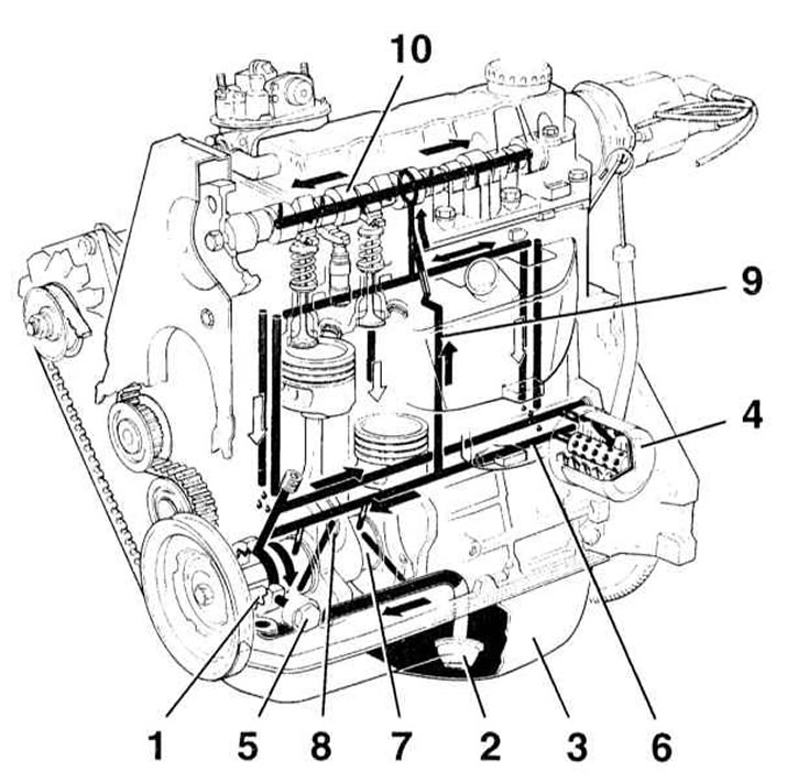
1 - gear (rotary) oil pump
2 - Oil intake
3 - Oil pan
4 - Full flow oil filter
5 - Pressure reducing valve
6 - Main oil flow
7 — a radical neck of a cranked shaft
8 - Connecting rod neck of the crankshaft
9 - Maslotok vertical oil supply
10 - Camshaft neck
The model range of Opel Astra/Zafira is distinguished by the extreme breadth of the range of engines offered to the attention of consumers. A complete list of engines used for completing the considered engine models is given in Specifications at the beginning of this chapter. Due to limited space, this manual presents only some of the most typical representatives of each class of used engines, namely: 1.6 liter SOHC gasoline 8-valve engine (manufacturer code X16SZR), a range of gasoline 16-valve DOHC engines from 1.4 to 2.0 liters (manufacturer codes X14XE, X16XEL, X18XE1 and X20XEV, later modified with the X20XER engine used to power the Astra-OPS models); as well as 8-valve diesel engines with a volume of 1.7 l SOHC and DOHC (codes X17DTL and Y17DT respectively) and two representatives of turbocharged 16-valve SOHC diesel engines with a volume of 2.0 liters (codes X20DTL/Y20DTL low pressure turbo and Y20DTH high pressure turbo). At the beginning of the chapter are Specifications outlining the detailed technical specifications of the engines listed.
1.6L SOHC petrol engines
Inline 4-cylinder 8-valve engine, single overhead camshaft (SOHC). Mounted transversely at the front of the vehicle. The transmission assembly is located to the left of the engine and transmits the torque developed by the latter to the front wheels of the car.
The cylinder block is made of aluminum alloy and equipped with dry liners.
Observe the prescribed tightening torques for screwed connections, as cast aluminum is a soft material and overtightening component fasteners can damage the threaded holes!
The crankshaft rotates in five main bearings equipped with plain bearings. Thrust half rings regulating the axial play of the shaft are installed on the central (third) shaft support.
The connecting rods are mounted on the working journals of the crankshaft equipped with plain bearings and horizontally cut lower heads. The connecting rods are attached to the pistons by means of piston pins planted in their upper heads, the pins in the pistons have a floating fit. The aluminum cast pistons are equipped with three piston rings, two compression rings and one (lower) oil scraper.
The camshaft rotates in a bed mounted on top of the cylinder head and is driven by the crankshaft via a rubber toothed belt (the same belt is used to drive the water pump). The eccentric cams of the camshaft act on the valve actuator levers, the working ends of which rest against the ends of the spring-loaded valve stems threaded into the guide bushings and equipped with oil caps. Opposite ends of the levers rest on hydraulic compensators that automatically adjust valve clearances.
The engine lubrication system is powered by a gear oil pump driven by the crankshaft trunnion. Oil is drawn through a strainer-equipped oil pick-up from the engine sump and filtered by a full-flow replacement oil filter. The oil moves along the oil flows provided in the casting of the block and is distributed in two main directions: to the bearings of the crankshaft and camshaft. Oil is supplied to the bearings under pressure through special drillings in the shaft bodies. Lubrication of the camshaft cams and valve components, as well as other internal engine components, is carried out by the splash method.
Typical diagram of the functioning of the lubrication system - see illustration General scheme of operation of the engine lubrication system used to complete Opel Astra / Zafira cars.
The output of crankcase gases from the engine block is carried out using a semi-closed ventilation system. Gases are discharged through the cover of the gas distribution mechanism and enter the intake pipeline through a special hose.
Gasoline engines 1.4—2.0 L DOHC
Engine 4-cylinder in-line, 16-valve, equipped with two overhead camshafts (DOHC), mounted transversely in front of the vehicle. The drive is carried out on the front wheels by means of a transmission assembly fixed to the left of the engine.
Some of the 2.0 engines are equipped with a balance assembly consisting of two additional shafts, providing a reduction in the intensity of vibrations associated with the functioning of the crankshaft. The assembly is installed between the cylinder block and the oil pan (see more details. Removal, installation and adjustment of the crankshaft balancing mechanism (engines 2.0 l).
The design of the cylinder block and connecting rod and piston groups is similar to that described above for SOHC engines.
Both camshafts rotate in the head of the block and are driven from the crankshaft by a rubber toothed belt, which also serves to drive the water pump. The intake and exhaust valves are driven directly from the eccentric cams of the respective camshafts through tappets equipped with hydraulic valve clearance compensators.
The operation of the lubrication and crankcase ventilation systems is also similar to that described above for SOHC engines.
Diesel engines 1.7L SOHC
Engine 4-cylinder in-line, 8-valve, single overhead camshaft (SOHC), mounted transversely in front of the vehicle. The transmission assembly is attached to the engine on the left and transmits torque to the front wheels.
The cylinder block is made by cast iron with cylinders molded directly in its body (block with dry sleeves).
The crankshaft rotates in five main bearings equipped with plain bearings. Thrust half rings regulating the axial play of the shaft are planted in the upper half of the central (third) supports. A distinctive feature of this engine is the use of a cast screed of the crankshaft bearings.
The connecting rods are mounted on the shaft with their lower horizontally cut heads equipped with plain bearings. Cast aluminum pistons are connected to the connecting rods by means of piston pins floating freely in the upper heads of the connecting rods and fixed in the piston bosses with retaining rings. Each piston is equipped with three piston rings - two compression and one (lower) oil scraper.
The intake and exhaust valves are spring-loaded and move in guide bushings pressed into the cylinder head. The camshaft is driven from the crankshaft by means of a toothed belt and rotates directly in the block head. The valve drive is carried out from the camshaft using drive levers installed directly under the cams. The selection of valve clearances is carried out automatically by equipping the support legs of the drive levers with hydraulic compensators.
The lubrication system is organized similarly to that described above for gasoline engines, with the only difference being that in order to increase the intensity of cooling of the piston bottoms, an oil sprayer is installed in the base of each of the cylinders of the block. To maintain normal oil temperature at increased loads, the engine is additionally equipped with an oil cooler.
Diesel engines 1.7L DOHC
Engine 4-cylinder in-line, 16-valve, equipped with two overhead camshafts (DOHC), mounted transversely in front of the vehicle. The drive is carried out on the front wheels by means of a transmission assembly fixed to the left of the engine.
The design of the cylinder block and connecting rod and piston groups is similar to that described above for 1.7 l SOHC engines, excluding the crankshaft main bearing tie.
The intake camshaft rotates in the timing case and is driven by a timing belt directly from the crankshaft. The drive of the exhaust camshaft is carried out by means of a gear transmission from the intake shaft.
The cams of the shafts act on the rods of the valves placed in the guide bushings through the tappets equipped with adjusting washers. Valve clearances are set manually by selecting washers of the required thickness.
The lubrication system is organized similarly to that described above for gasoline engines. In order to maintain normal oil temperature at increased loads, the engine is additionally equipped with an oil cooler.
Diesel engines 2.0L SOHC
two liter (1994 cm3) the engine is one of the latest developments from Opel and is a 4-cylinder in-line, 16-valve design with a single overhead camshaft (SOHC). The engine is installed transversely in the front of the car, a transmission assembly is connected to it on the left, through which the torque is transmitted to the front drive wheels.
The crankshaft rotates in five main bearings. Support semi-rings, which regulate the value of the axial play of the shaft, are installed in the third support.
The connecting rods are mounted on the crankshaft journals by horizontally cut and equipped with plain bearing shells by lower heads. The piston pins have a floating fit in the upper heads of the connecting rods and are secured with circlips in bosses on the piston walls. The aluminum cast pistons are equipped with three piston rings: two compression rings and one (lower) oil scraper.
The cylinder block is cast in gray cast iron. Cylinders form a single unit with the block (dry sleeves).
The intake and exhaust valves are spring-loaded and move in guide bushings pressed into the cylinder head.
The camshaft is driven from the crankshaft by a two-row chain drive: the lower chain drives the high pressure fuel pump (injection pump) directly from the crankshaft, with the help of the upper chain, the camshaft drive is organized from the upper chain ensures the rotation of the camshaft from the injection pump.
A single camshaft rotates directly in the cylinder head and drives sixteen by means of drive levers and pushers equipped with hydraulic compensators. The valve actuation levers are mounted directly below the cams and each actuate two valves. The selection of valve clearances is done automatically.
The lubrication system is organized similarly to that described above for a 1.7 liter engine.
All engines
The list of repair work performed without removing the engine from the car
The following repairs can be carried out without removing the engine from the vehicle:
1. Compression check;
2. Removing and installing the timing cover;
3. Removal and installation of the timing cover;
4. Removal and installation of timing drive components (belt/ chains, cogwheels/ sprockets);
5. Removal and installation of the timing belt / chain tensioner and chain guides diesel engines (engines 2.0 l);
6. Removal and installation of the camshaft (ov) and valve levers / tappets);
7. Valve clearance adjustment (diesel engines 1.7 l DOHC);
8. Removal and installation of the cylinder head;
9. Removal and installation of pistons with connecting rods *;
10. Removal and installation of the oil pan;
11. Removal, refurbishment and installation of the oil pump;
12. Removal and installation of the oil cooler (with appropriate equipment);
13. Replacing the crankshaft seals;
14. Checking the condition and replacing the suspension mounts of the power unit;
15. Removal, condition check and installation of the flywheel / drive plate
*Although after removing the head and sump (without removing the engine) it becomes possible to dismantle the connecting rod and piston assemblies, this opportunity should not be abused due to the difficulties associated with the need to maintain cleanliness and carry out a number of preparatory procedures. In view of the above, for a description of this procedure, see General and overhaul of the engine.
Before starting work, thoroughly clean the engine compartment and external surfaces of the power unit using one of a wide range of special solvents. This treatment will prevent dirt from getting inside the engine.
If necessary, depending on the nature of the work ahead, the hood can be removed in order to provide freedom of access to the components to be serviced (see chapter Body), - to avoid accidental damage to the paintwork, cover the fenders of the car with special covers, or just old blankets.
Visitor comments