


Contents: Clutch release bearing ⬇ Clutch slave cylinder ⬇ Repair of the working hydraulic…⬇ Clutch Damping Cylinder ⬇ Removal and installation the main…⬇ Repair of the main hydraulic cylinder ⬇ Clutch pedal and bearing support ⬇
Clutch release bearing
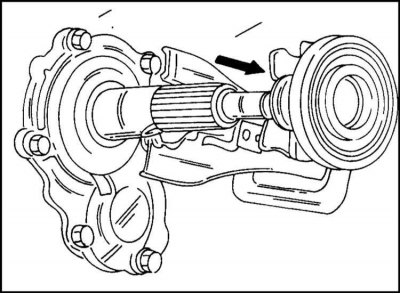
The clutch release bearing can only be removed and installed with the gearbox removed. The bearing is secured to the housing with spring clamps. After removing the clamps, remove the pin and lever. Remove the bearing from the gearbox housing as shown in the illustration.
Press the bearing out of the housing. Disconnect the lever pin from the gearbox shaft cover.
Press on a new bearing. In this case, make sure that the thrust side of the bearing is directed in the direction opposite to the housing. Install the clutch release lever pin onto the cover.
Lubricate the inner bore of the bearing housing, the bushing in the gearbox shaft cover and the ball joint of the lever with grease. Reinstall the bearing, clutch release lever and rubber boot. Note the correct position of the clamps on the arm behind the ball joint.
Clutch slave cylinder
Installation and removal of the hydraulic cylinder is performed as follows.
1. Fill the main hydraulic cylinder reservoir with fluid up to the upper edge. Cover the hole with polyethylene and screw on the plug. This prevents liquid from leaking out of the cylinder. If it is necessary to drain the liquid from the system, then proceed as follows:
2. Place the hose on the air bleed nipple of the working cylinder. Place the other end of the hose into the container and unscrew the fitting a few turns. With the help of an assistant, press the pedal until all the fluid comes out.
3. Unscrew the hollow hose mounting bolt and remove the sealing washers.
4. Unscrew the two bolts and remove the cylinder.
The cylinder is installed in the reverse order of its removal. In this case, it is necessary to pay attention to the following:
1. Tighten the cylinder mounting bolts for the MSG gearbox to 28 Nm; for the MUA gearbox, tighten to 45 Nm.
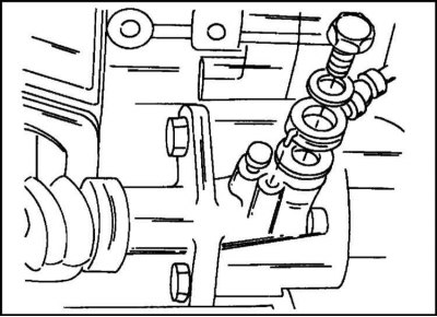
2. Tighten the elbow joint bolt, installing two new O-rings (illustrated). The correct position of the hose ring is ensured by the pin. Bolt tightening torque 35 Nm.
[Text copied from a web portal: www.OPELBOOK.ru]
3. Bleed the hydraulic system and adjust the clutch pedal height as described below.
Repair of the working hydraulic cylinder
During repairs, the hydraulic cylinder is replaced with a repair kit. A defect such as corrosion of the outer surface is grounds for replacing the cylinder.
When assembling the internal parts of the cylinder (except for protective caps) are lubricated with brake grease.
When installing the caps, check the ease of movement of the piston.
Clutch Damping Cylinder
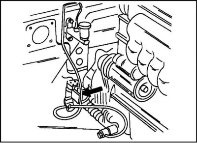
1. The clutch damper cylinder is located in the location shown in the illustration. Before removing the damper cylinder, close the reservoir or drain the fluid from the system as described above. To do this, disconnect the hoses from the cylinder and unscrew the holder nuts.
2. When installing, tighten the bolts to a torque of 8 Nm. Tighten the hose connections to a torque of 20 Nm.
3. After installation, remove air from the system and check the fluid level in the tank, top up the fluid if necessary.
Removal and installation the main hydraulic cylinder
To remove the main hydraulic cylinder, remove the clutch pedal and holder. The cylinder is removed as follows:
1. Drain the fluid from the system as described above or suck the fluid out of the reservoir.
2. Disconnect the hose from the cylinder. Make sure that any leaking liquid does not come into contact with other parts.
3. Remove the clutch pedal and bearing support.
4. Unscrew the two nuts and remove the cylinder.
5. Installation of the master cylinder is performed in the reverse order of removal. Tighten the cylinder mounting nuts to 15 Nm. Finally, bleed the system and check the fluid level in the reservoir. Add fluid if necessary.
Repair of the main hydraulic cylinder
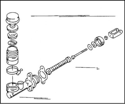
1. If a repair kit is available, the hydraulic cylinder is repaired in a known manner. Unscrew the rod with the fork (lock-nut) and measure the size between the center of the pin hole and the mating surface of the cylinder body (write down the size). This dimension will be needed later during assembly. If, when disassembling the cylinder, traces of corrosion or any other defects are found on its working surface (bullies, etc.), the cylinder is replaced. The disassembled cylinder is shown in the illustration.
2. By disconnecting the hose clamp, you can remove the tank from the cylinder.
All internal parts are lubricated with brake fluid or grease (except for the protective cap). When assembling the cylinder, keep the previously recorded dimension and tighten the lock nut. Check the piston for freedom of movement.
Clutch pedal and bearing support
The operation is quite labor-intensive.
1. Remove the lower instrument panel trim on the driver's side.
2. Remove the driver's side air duct.
3. Remove the spring clip at the junction of the main hydraulic cylinder rod and the clutch pedal. Remove the support pin and disconnect the fork from the pedal.
4. Remove the four bolts and remove the bearing support. Once the pedal pivot pin has been removed, the pedal and return spring can be removed. Pay attention to the spring mount.
5. Remove the pedal stop bolt and lock nut.
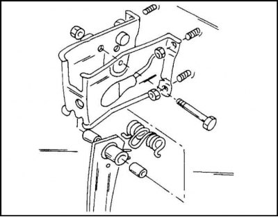
6. Installation of the parts in question is performed in the reverse order of removal. The fastening details are shown in the illustration. Check that the return spring is properly secured to the pedal and to the bearing support. The pedal pin mounting nut is tightened to a torque of 35 Nm, the bearing support mounting nuts to a torque of 21 Nm.
Finally, adjust the pedal height and travel as described below.
Visitor comments