
OpelBook.ru
Cars AvtoVAZ Cars Mitsubishi Cars BMW Cars Mercedes Cars Nissan Cars Toyota Cars Chevrolet
English Русский
Български
Беларускі
Український
Српски
Hrvatski
Română
Polski
Slovenský
Magyar
 |  Sitemap  |  Contacts  |    


Main Astra Corsa Insignia Kadett Omega Vectra Zafira Others Articles
Astra F (1991-1998, petrol) Astra G (1998-2004, petrol) Astra G (1998-2004) Astra H (2004-2009) Astra J (2009-2015, petrol)
  • Main
  • Astra
  • Astra H
  • Transmission
  • Automatic gearbox
  • Removal and installation of AT

Removal and installation of AT (Opel Astra H)

            0

Contents: Removal ⬇ Installation ⬇

Removal


1. Remove the crankcase guard (with appropriate equipment) and drain the ATF (see Section 4), then screw the drain plug back into its original place and tighten it to the required torque.

2. Remove the drive shafts (see Chapter 8) and, having suspended the power unit from above, remove the front subframe (see Chapter 10).

3. Remove the air cleaner with the intake ducts (see Chapter 4).

4. Release the lock (if provided) and carefully disconnect the selector cable from the AT lever. Release the cable sheath from the support bracket and move the cable to the side.

5. Unscrew the mounting bolt and remove the guide tube together with the oil level dipstick.

6. Follow the wiring harness from the transmission switches and sensors, release the clamps and disconnect the connectors. Release the wiring harnesses from all the provided intermediate clamps on the transmission case.

7. Loosen the mounting bolts and remove the electrical wiring and drive cable mounting bracket.

8. Disconnect the power unit from the right and left supports and remove the left support (see Chapter 2).

9. If equipped, disconnect the breather hose from the top of the transmission case. Remove the 3 upper transmission dome mounting bolts.

10. Support the transmission with a trolley jack (to distribute the load, place a wooden block between the jack head and the transmission housing).

11. After marking, disconnect the ATF cooling hoses from the front of the transmission case (release the clips by prying them up with a screwdriver) (see accompanying illustration). Put the clamps back in place and remove the sealing rings - the rings must be replaced without fail. Immediately plug the open ends of the hoses and fittings to prevent dirt from getting into the system.
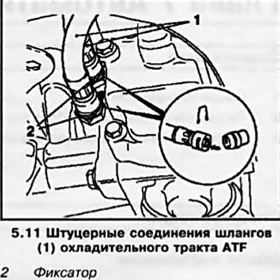


11. After marking, disconnect the ATF cooling hoses from the front of the transmission case…


12. Unscrew the mounting bolts and remove the front support of the power unit suspension (see Chapter 2).

13. Using a hoist and jack, lower the power unit by approximately 50 mm - try not to allow the communication lines laid under the transmission to be pressed.

14. Separate the service cover (see accompanying illustration) from the transmission, turning the torque converter, remove the plugs one by one and unscrew the 3 bolts securing it to the drive disk and disconnect the transformer from the disk. Then unscrew the 3 mounting bolts and disconnect the AT from the oil pan.
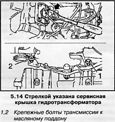
14. Separate the service cover (see accompanying illustration) from the transmission, turning the…


15. Support the entire transmission on the jack, then remove the 2 lower transmission-to-engine mounting bolts - try to remember the location of the bolts and the mounting brackets they secure. Again, make sure all communication lines are disconnected and nothing is blocking the transmission from being removed.


16. Move the jack and separate the transmission from the engine, completely removing it from the guide bushings. Lower the jack and remove the transmission from under the car! Be careful not to drop the torque converter or damage the transmission components. If the bushings are seated loosely in their sockets, remove them and put them in a safe place.

Note: When replacing the transmission, it is necessary to check the patency of the AT cooling tracts - blow out the heat exchanger and connecting lines with compressed air.


Installation


17. Installation is carried out in the reverse order of dismantling the components. Please note the following points:

Article posted on a web portal opelbook.ru
  • a) Before installation, run a tap through the threaded holes of the torque converter, completely removing traces of corrosion and old sealant from their threads (instead of a tap, you can use an old bolt of the appropriate size, after making a longitudinal cut in it);
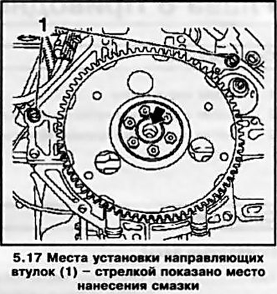
  • b) Make sure that the guide bushings are in place and lubricate the torque converter guide pin and the centering bushing on the crankshaft journal with molybdenum-containing grease (see accompanying illustration);
  • c) Ensure that the transmission is installed correctly on the engine, tighten all fasteners to the required torque;
  • d) Do not forget to replace the torque converter to drive plate mounting bolts;
  • e) Don't forget to replace the drive shaft seals (see Chapter 8);
  • f) Replace the sealing rings of the ATF cooling system line nipples, check that the tubes are securely fastened;
  • g) Be sure to replace the sealing element of the ATF dipstick guide tube.
g) Be sure to replace the sealing element of the ATF dipstick guide tube.


18. Finally, fill the transmission with the required amount of fresh ATF (see Chapter 1 and Section 4 of this Chapter) and adjust the selector cable (see Section 2).


This article is available at russian, bulgarian, belarusian, ukrainian, serbian, croatian, romanian, polish, slovak, hungarian
Checking the article: Simonov Timofey

Share information:

Previous articles
Opel Astra H: Automatic gearbox
Next articles

Checking the condition of the working fluid
Removal and installation the gear selection cable
Adjusting the gear selection mechanism
General information
4-speed automatic transmission specifications


Link to this page in different formats

Visitor comments


No comments yet


How much will 42 + 12 =


Astra J (2009-2015, petrol) 
  • General information
  • Vehicle device
  • User manual
  • Faults en route
  • Maintenance
  • Power unit
  • Engine repair
  • Cooling and lubrication system
  • Engine power system
  • Exhaust system
  • Transmission
  • Clutch
  • Car gearbox
  • Drive shafts
  • Chassis
  • Front suspension
  • Rear suspension
  • Steering
  • Brake system
  • Wheels and tires
  • Body
  • Exterior
  • Interior
  • Doors and windows
  • Body Care
  • Heating and air conditioning
  • Security systems
  • Electrical equipment
  • Equipment and devices
  • Lighting and signaling
  • Power devices
  • Electrical circuits
Astra H (2004-2009) 
  • General information
  • Introduction to the guide
  • Troubleshooting
  • User manual
  • Maintenance
  • Power unit
  • Engine repair
  • Cooling and heating
  • Power and exhaust system
  • Ignition system
  • Launch and charge system
  • Transmission
  • Mechanical gearbox
  • Automatic gearbox
  • Drive shafts
  • Chassis
  • Brake system
  • Car suspension
  • Steering
  • Body
  • Interior
  • Exterior
  • Electrical equipment
  • Equipment and devices
  • Electrical circuits
Astra G (1998-2004) 
  • General information
  • Introduction to manual
  • User manual
  • Maintenance
  • Power unit
  • SOHC gasoline engines
  • DOHC gasoline engines
  • Diesel engines 1.7 and 2.0
  • Engine repair
  • Cooling system
  • Supply system
  • Injection system (gasoline)
  • Injection system (diesel)
  • Exhaust system
  • Charge and launch system
  • Ignition system (gasoline)
  • Preheat system (diesel)
  • Transmission
  • Manual gearbox
  • Automatic gearbox
  • Clutch
  • Drive shafts
  • Chassis
  • Brake system
  • Wheel suspension
  • Steering
  • Body
  • Exterior
  • Interior
  • Doors and windows
  • Ventilation and heating
  • Electrical equipment
  • Equipment and devices
  • Electrical circuits
Astra G (1998-2004, petrol) 
  • General information
  • User manual
  • Car care
  • Maintenance
  • Power unit
  • Single shaft engines
  • Twin shaft engines
  • Engine repair
  • Cooling and heating
  • Fuel and exhaust systems
  • Starting and charging system
  • Ignition system
  • Transmission
  • Clutch
  • Mechanical gearbox
  • Automatic gearbox
  • Drive shafts
  • Chassis
  • Brake system
  • Car suspension
  • Steering
  • Body
  • Interior
  • Exterior
  • Electrical equipment
  • Equipment and devices
  • Wiring diagrams Opel Astra
  • Wiring diagrams Opel Zafira
Astra F (1991-1998, petrol) 
  • General information
  • Maintenance
  • Power unit
  • Engine in car
  • Engine removed
  • Cooling system
  • Heating and ventilation
  • Fuel supply (carburetor)
  • Fuel supply (injector)
  • Emission control
  • Ignition system
  • Transmission
  • Clutch
  • Mechanical gearbox
  • Automatic gearbox
  • Drive shafts
  • Chassis
  • Brake system
  • Car suspension
  • Steering
  • Body
  • Exterior
  • Interior
  • Electrical equipment
  • Equipment and devices
  • Electrical circuits
OpelBook.ru © 2017–2026 · Mobile version · · Sitemap: EN BG BY UA RS HR RO PL SK HU · Feedback · Site search
Astra F, petrol · Astra G, petrol · Astra G · Astra H · Astra J, petrol · Corsa B · Corsa C, petrol · Corsa C · Insignia A · Kadett D · Kadett E · Omega A · Omega B · Omega B2 · Vectra A, petrol · Vectra A · Vectra B, petrol · Vectra B · Vectra C · Zafira A, petrol · Frontera A, petrol · Frontera B · Ascona C · Vivaro A ·
We want your visit to be comfortable 🤝! We use cookies 🍪 to make that happen.