
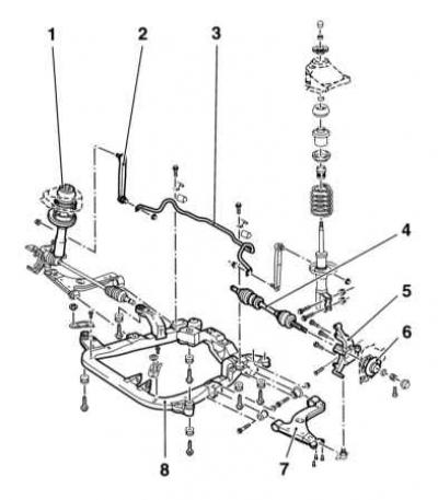
1 — The top support of a rack
2 - Vertical thrust (rack) anti-roll bar
3 — a bar of the stabilizer of cross stability
4 - Drive shaft
5 - Swivel fist
6 - Wheel hub
7 - Control arm suspension
8 - Subframe
Rear suspension design
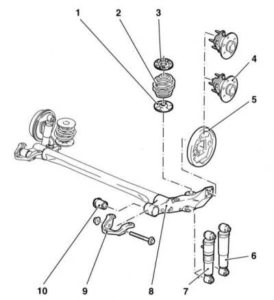
1 - Lower saddle of the helical spring
2 - Helical spring
3 — the Top saddle of a screw spring
4 - Hub Assembly
5 - Brake drum
6 - Telescopic shock absorber (models without rear height adjustment)
7 - Telescopic shock absorber (models with adjustable rear ride height - option)
8 - Torsion beam rear suspension
9 — an arm of fastening of the suspension arm
10 - rubber-metal hinge
Steering gear design
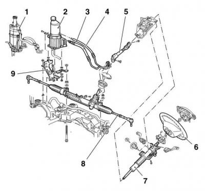
1 - Delphi steering pump
2 - TRW steering pump
3 - Return hydraulic line
4 - Pressure hydraulic line
5 - Intermediate shaft
6 - steering wheel
7 - Steering column
8 - Tie rod
9 - Steering pump support bracket
Front suspension fully independent with subframe and lower control arms, MacPherson struts and anti-roll bar (see illustration Front suspension design). The struts consist of gas-filled telescopic shock absorbers and coil springs and are attached with their upper ends to reinforced supports on the mudguards of the front fenders, and with the lower assemblies of the steering knuckles. The hubs are equipped with non-adjustable bearings. The lower parts of the steering knuckles are connected to the lower suspension arms by means of ball bearings. Ball bearings are attached to the levers with bolts, and to the steering knuckles - with bolted clamps. The inner ends of the levers are attached to the subframe by means of rubber-metal hinges, limiting the lateral and longitudinal movement of the front wheels. An anti-roll bar is standard on all models. The stabilizer is mounted on a subframe and connected to the suspension struts by means of two vertical rods (racks).
The torsion beam of the semi-independent rear suspension consists of two trailing arms and a connector (see illustration Rear suspension design). In the rear part of the suspension arms, there are mountings for mounting shock absorbers and spring assemblies, as well as vertical flanges to which the hub assemblies of the rear wheels are bolted together with the brake shields. At the front ends of the levers, bushings are equipped with rubber-metal hinges pressed into them. Bolts are threaded through the hinges, fixing the suspension arms in brackets bolted to the side members of the body. The upper ends of the shock absorbers are attached to the load-bearing elements of the bottom of the body. The springs are installed separately from the shock absorbers and are fixed by two saddles, one of which is attached to the flange on the lever, the other to the bottom of the car. Wheel bearings are built into non-separable hub assemblies. Station wagon models are equipped with a manual rear ride height adjustment system. The system is controlled by supplying compressed air to the shock absorbers. The amount of clearance depends on the pressure in the shock absorbers, which is regulated by a valve located in the luggage compartment.
Steering gear - ordinary rack and pinion type, with shock-absorbing steering column (see illustration Steering gear design). The column is connected to the mechanism by means of an intermediate shaft equipped with crosses. The sliding upper section of the steering column is equipped with a lock that blocks the steering gear. When locked, the lock allows the steering column to rotate with a force of 200 Nm, which prevents the lock pin from breaking. In this case, the amount of torque required to rotate the steering wheel makes it impossible to control the car. The steering mechanism is mounted on the front suspension subframe. Steering rods are attached to the steering knuckle levers with the help of steering tips. Power steering system is standard on all models (power steering). The electro-hydraulic steering pump is mounted directly on the steering gear and requires no maintenance. The hydraulic fluid reservoir is built into the pump assembly.
Often, during the maintenance of suspension components, one has to deal with hard-to-return fasteners. «sticking» fasteners due to the fact that they are constantly exposed to external influences, are in contact with water, dirt, soot and other substances that contribute to the development of corrosion. In order to facilitate the procedure for giving such «stuck» fasteners, it should be impregnated in advance with a copious amount of penetrating oil. Scouring exposed threaded parts of fasteners with a stiff wire brush also helps loosen rusted nuts. Sometimes, in especially severe cases, for letting go «stuck» bolts / nuts, you can use a drift. The drift rests against the edge of the slot of the nut / bolt head, then sharp blows are applied to its opposite end with a hammer. Make sure that the drift does not break, try not to damage the thread with inaccurate blows. Heating a non-retractable fastener and the surrounding surface of the component with a blowtorch or gas burner is also a fairly effective method, although the drafters of this Guide do not recommend resorting to this technology unless absolutely necessary due to its potential danger associated with the possibility of fire and the risk of burns. To increase the torque when releasing fasteners, various kinds of extensions, gates and pipe nozzles are used on them. However, remember that you should not use this kind of amplifying devices complete with equipped «ratchet» drive - the risk of failure of the ratchet mechanism is too great. Sometimes a nut/bolt starts to give in after it has been pre-tightened slightly in a clockwise direction. All fasteners, the release of which required the use of extraordinary measures during assembly, must be replaced!
After giving away, carefully check the condition of the fastener and, if necessary, replace it with elements of the same size. When assembling, tighten the fasteners of the suspension and steering components strictly with the required force.
Never try to straighten deformed suspension and steering components - replace defective parts with new ones!
Since the maintenance procedures for the suspension components are performed under the vehicle, care should be taken in advance to raise the vehicle and fix it in a raised position (prepare a reliable jack and props).
Under no circumstances should you carry out any work under the vehicle, which has only been secured in the raised position with a jack!
Precautionary measures
An airbag is built into the hub of the steering wheel. To ensure that the airbag deploys properly in a crash, and to avoid the risk of injury from accidental airbag deployment, certain precautions must be taken (see also Chapter Onboard electrical equipment):
- Be sure to disconnect the negative battery cable before starting work on the airbag or near the SRS wiring route, work should be done at least one minute after disconnecting the battery, time is needed for the backup power supply capacitor to discharge.
- Do not allow the airbag module to exceed 90°C. Do not turn the removed airbag module upside down.
- Avoid contact with solvents and detergents on the surface of the module - use only a clean, slightly damp cloth to wipe the steering wheel.
- The SRS control unit and airbag modules are sensitive to directional overloads (blows) and after a fall from a height of more than 50 cm must be replaced.
- Before carrying out welding work on the vehicle, be sure to disconnect the electrical wiring of the SRS control unit.
- On models equipped with passenger airbags, to avoid injury, do not install any accessories or place any foreign objects in the airbag deployment area.
Visitor comments