
OpelBook.ru
Cars AvtoVAZ Cars Mitsubishi Cars BMW Cars Mercedes Cars Nissan Cars Toyota Cars Chevrolet
English Русский
Български
Беларускі
Український
Српски
Hrvatski
Română
Polski
Slovenský
Magyar
 |  Sitemap  |  Contacts  |    


Main Astra Corsa Insignia Kadett Omega Vectra Zafira Others Articles
Astra F (1991-1998, petrol) Astra G (1998-2004, petrol) Astra G (1998-2004) Astra H (2004-2009) Astra J (2009-2015, petrol)
  • Main
  • Astra
  • Astra G
  • Chassis
  • Wheel suspension
  • Checking the condition and replacing the hub assembly

Checking the condition and replacing the hub assembly (Opel Astra G)

            0

Contents: Examination ⬇ Replacement ⬇

Examination


1. Set the parking brake, jack up the front of the vehicle and support it. Rotate the wheel manually, listening for sounds from the wheel bearing. Grasp the wheel with your hands and rock it to detect signs of play in the bearing - try not to confuse play in the bearings with play in the joints of the suspension and steering components (see Chapter Routine maintenance).

Replacement


1. Set the parking brake, jack up the front of the vehicle and place it on stands. Remove the corresponding front wheel.

2. Remove the brake caliper and, without disconnecting the flexible hydraulic hose, tie it to the side to the suspension elements, - release the hose from the support bracket and remove it, having first released the retainer, - remove the brake disc (see Chapter Brake system).
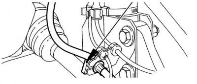
2. Remove the brake caliper and, without disconnecting the flexible hydraulic hose, tie it to the…


3. Remove the protective cap of the hub nut, block the hub from turning by holding it with a tire iron inserted between two temporarily screwed-in wheel bolts, remove the cotter pin and loosen the nut.

The nut is tightened very tightly.


4. Remove the cotter pin and loosen the tie rod end mounting nut. Using a puller, press the ball joint of the end out of the lever on the steering knuckle. Loosen the mounting nut and disconnect the vertical stabilizer link from the suspension strut.


5. Unscrew the bolt of the clamp securing the ball joint pin to the knuckle - try to remember the installation position of the bolt.

The authors of this Manual recommend replacing the bolt and nut without fail.


7. Use a chisel or a large screwdriver to loosen the clamp at the bottom of the knuckle.

8. By pressing the lower suspension arm, release the ball joint pin from the clamp. Move the strut to the side and release the lever - try not to damage the ball joint boot.
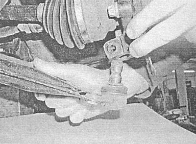
8. By pressing the lower suspension arm, release the ball joint pin from the clamp. Move the strut…


9. On aBS equipped models disconnect the wiring from the wheel sensor.
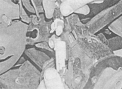
9. On aBS equipped models disconnect the wiring from the wheel sensor.


10. Move the knuckle outward, pushing the drive shaft journal out of the hub - if necessary, knock the shaft out with a hammer through a brass drift.

11. Mark the relative positions of the outer bearing race, cam and base plate.


12. From the back of the knuckle, unscrew the three bearing assembly mounting bolts - the bolts must be replaced during assembly.
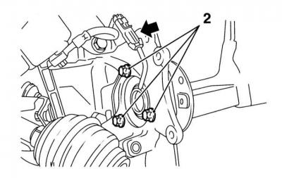
12. From the back of the knuckle, unscrew the three bearing assembly mounting bolts - the bolts…


13. Remove the bearing assembly and base plate (3) from the knuckle (4), being careful not to damage the wheel sensor wiring.
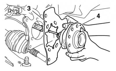
13. Remove the bearing assembly and base plate (3) from the knuckle (4), being careful not to…


14. The bearing unit is built into the hub assembly and its dismantling is not possible. In the event of failure of any of the hub elements, the entire assembly must be replaced.

15. After cleaning the mating surfaces, press the base plate against the knuckle - make sure that the mounting marks applied during the dismantling of the components are correctly aligned. Lightly lubricate the threaded part of the new mounting bolts with a locking anaerobic sealant, then screw them in and tighten them in several stages to the required force (see Fig. Specifications).


16. Pull the knuckle outward and insert the drive shaft journal into the hub. Install the washer, then screw on the nut and tighten it lightly, achieving a complete fit of the shaft journal in the hub. The final tightening of the nut is done later (see below).

17. On aBS equipped models connect the wiring to the wheel sensor, press down the lower arm and insert the ball joint pin into the knuckle clamp.

18. Remove the expansion wedge from the clamp lock and insert a new bolt. Tighten the nut to the required torque.

19. Place the steering rod end in the knuckle and tighten the nut to the required torque. If necessary, secure the nut with a new cotter pin. Connect the vertical stabilizer bar link to the suspension strut and tighten the nut to the required torque.

20. Having blocked the hub from turning with a tire iron, tighten its hub nut in several stages with the required force (see Specifications). Install a new cotter pin and bend its outer leg around the nut. Bend the inner leg of the cotter pin inward, then bite off the free end.

21. Install the hub nut protective cap.

22. Reinstall the brake components (see Chapter Brake system).

[Original source is on the website: OPELBOOK]

23. Install the front wheel, lower the vehicle to the ground and tighten the wheel bolts to the required torque.


This article is available at russian, bulgarian, belarusian, ukrainian, serbian, croatian, romanian, polish, slovak, hungarian
Checking the article: Pavlovsky Nikolay

Share information:

Previous articles
Opel Astra G: Wheel suspension
Next articles

Removal and installation the steering knuckle
Suspension and steering specifications
General information about suspension and steering
Removal and installation the front subframe
Removal, repair and installation of the front suspension strut
Removal and installation the front anti-roll bar
Removal, repair and installation of the lower arm of the front suspension
Replacing the lower ball joint
Removal and installation the rear hub assembly


See similar ones from other Opel car manuals:
▶ Checking the condition and replacing the hoses located in… Opel Corsa B (1993-2000)
▶ Checking the condition and replacing the multi-rib drive… Opel Vectra C (2002-2008)
▶ Accessory Drive Belt — Checking Condition and Replacing Opel Zafira A (1999-2005, petrol)
▶ Checking the condition and replacing the engine compartment… Opel Frontera A (1991-1998, petrol)
▶ Cleaning and checking the technical condition of the… Opel Insignia A (2008-2017)
Link to this page in different formats

Visitor comments


No comments yet


How much will 11 + 27 =


Astra J (2009-2015, petrol) 
  • General information
  • Vehicle device
  • User manual
  • Faults en route
  • Maintenance
  • Power unit
  • Engine repair
  • Cooling and lubrication system
  • Engine power system
  • Exhaust system
  • Transmission
  • Clutch
  • Car gearbox
  • Drive shafts
  • Chassis
  • Front suspension
  • Rear suspension
  • Steering
  • Brake system
  • Wheels and tires
  • Body
  • Exterior
  • Interior
  • Doors and windows
  • Body Care
  • Heating and air conditioning
  • Security systems
  • Electrical equipment
  • Equipment and devices
  • Lighting and signaling
  • Power devices
  • Electrical circuits
Astra H (2004-2009) 
  • General information
  • Introduction to the guide
  • Troubleshooting
  • User manual
  • Maintenance
  • Power unit
  • Engine repair
  • Cooling and heating
  • Power and exhaust system
  • Ignition system
  • Launch and charge system
  • Transmission
  • Mechanical gearbox
  • Automatic gearbox
  • Drive shafts
  • Chassis
  • Brake system
  • Car suspension
  • Steering
  • Body
  • Interior
  • Exterior
  • Electrical equipment
  • Equipment and devices
  • Electrical circuits
Astra G (1998-2004) 
  • General information
  • Introduction to manual
  • User manual
  • Maintenance
  • Power unit
  • SOHC gasoline engines
  • DOHC gasoline engines
  • Diesel engines 1.7 and 2.0
  • Engine repair
  • Cooling system
  • Supply system
  • Injection system (gasoline)
  • Injection system (diesel)
  • Exhaust system
  • Charge and launch system
  • Ignition system (gasoline)
  • Preheat system (diesel)
  • Transmission
  • Manual gearbox
  • Automatic gearbox
  • Clutch
  • Drive shafts
  • Chassis
  • Brake system
  • Wheel suspension
  • Steering
  • Body
  • Exterior
  • Interior
  • Doors and windows
  • Ventilation and heating
  • Electrical equipment
  • Equipment and devices
  • Electrical circuits
Astra G (1998-2004, petrol) 
  • General information
  • User manual
  • Car care
  • Maintenance
  • Power unit
  • Single shaft engines
  • Twin shaft engines
  • Engine repair
  • Cooling and heating
  • Fuel and exhaust systems
  • Starting and charging system
  • Ignition system
  • Transmission
  • Clutch
  • Mechanical gearbox
  • Automatic gearbox
  • Drive shafts
  • Chassis
  • Brake system
  • Car suspension
  • Steering
  • Body
  • Interior
  • Exterior
  • Electrical equipment
  • Equipment and devices
  • Wiring diagrams Opel Astra
  • Wiring diagrams Opel Zafira
Astra F (1991-1998, petrol) 
  • General information
  • Maintenance
  • Power unit
  • Engine in car
  • Engine removed
  • Cooling system
  • Heating and ventilation
  • Fuel supply (carburetor)
  • Fuel supply (injector)
  • Emission control
  • Ignition system
  • Transmission
  • Clutch
  • Mechanical gearbox
  • Automatic gearbox
  • Drive shafts
  • Chassis
  • Brake system
  • Car suspension
  • Steering
  • Body
  • Exterior
  • Interior
  • Electrical equipment
  • Equipment and devices
  • Electrical circuits
OpelBook.ru © 2017–2026 · Mobile version · · Sitemap: EN BG BY UA RS HR RO PL SK HU · Feedback · Site search
Astra F, petrol · Astra G, petrol · Astra G · Astra H · Astra J, petrol · Corsa B · Corsa C, petrol · Corsa C · Insignia A · Kadett D · Kadett E · Omega A · Omega B · Omega B2 · Vectra A, petrol · Vectra A · Vectra B, petrol · Vectra B · Vectra C · Zafira A, petrol · Frontera A, petrol · Frontera B · Ascona C · Vivaro A ·
We want your visit to be comfortable 🤝! We use cookies 🍪 to make that happen.