
Specialists of Opel branded service stations use special conductors to combine the power unit with the subframe. If such devices are not at hand, then before starting to dismantle the components, their position relative to each other should be marked.
You will need the help of an assistant.
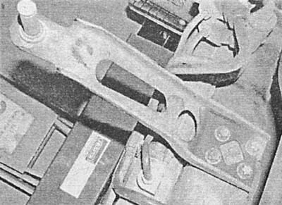
Subframe mounting bolt pattern
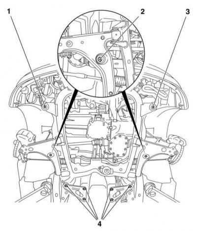
1, 3 - Front bolts
2 - Side bolts
4 - Rear bolts
Removing
1. Bring the front wheels of the car into a straight line, remove the key from the ignition and lock the steering wheel.
2. In the driver's footwell, remove the bolt that secures the bottom of the intermediate steering column shaft to the steering gear input shaft. Separate the intermediate shaft and take it to the side.
3. Remove the battery from the mounting tray (see chapter Engine electrical equipment).
4. On Zafira models at the rear of the engine compartment, remove the rubber seal and plastic cover. Give fixing nuts and remove the main cover from a partition.
5. Fasten the radiator to the front panel by threading two bolts into the side mounts - the lower, rubber radiator mounts are installed on the subframe.
6. Remove the cover from the relay mounting block on the left side of the engine compartment and remove the power steering system fuse from its seat. Release the latches, disconnect the fuse block from the common block and remove it along with the wiring.
7. Loosen the fixing nut and disconnect the steering wiring ground bus from the body panel, - try to remember the wiring diagram, then lower the latter down onto the steering gear housing.
8. Hang the power unit from above, - two lifting eyes are located on the left side of the cylinder head, one on the right (see chapter Engine).
9. Engage the parking brake, jack up the vehicle and place it on jack stands. Remove both front wheels. If equipped, remove the crankcase protection and steering gear heat shield.
10. Remove the front bumper (see chapter Body).
11. Remove sections of protection of an arch of the right forward wheel.
12. Disconnect the vertical anti-roll bars from the suspension struts on both sides.
13. Disconnect the tie rod ends from the steering knuckle arms (see Removal and installation of tips of steering draughts).
14. Turn out bolts of coupling collars of a rotary fist and release from them fingers of the bottom spherical support.
15. Remove the system downpipe, catalytic converter and middle section of the exhaust system (see chapter Power and exhaust systems).
16. Try to remember the installation scheme of the steering mechanism above the rear support of the power unit, then separate the latter from the support bracket on the subframe (see chapter automatic transmission).
17. Separate the rear support of the power unit from the transmission case.
18. Turn out the central bolt of a forward support of a suspension bracket of the power unit.
19. On models equipped with A/C, Disconnect the resonator from the front right section of the subframe.
20. Support the subframe with a trolley jack, - in order to distribute the load, lay a wooden block on the head of the jack (ideally you should use a special bed).
21. Clearly mark the position of the subframe and its mounting bolts relative to the car body - specialists use special conductors during installation.
22. Turn out bolts of fastening of a stretcher. The bolts have different lengths - try to remember the location of each one. The general layout of the fasteners is as follows: two bolts in front, two bolts above the lower suspension arms and six bolts on triangular brackets (see illustration Subframe mounting bolt pattern).
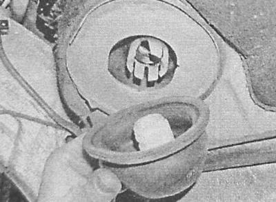
23. With the help of an assistant, lower the subframe, - try not to damage the electrical wiring of the steering pump. When lowering the subframe, release the steering shaft from the rubber bushing in the vehicle floor.
A - Releasing the steering shaft from the bushing in the bottom of the vehicle
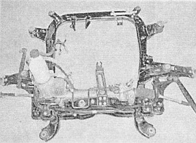
B - Front suspension subframe, removed from the vehicle
A.
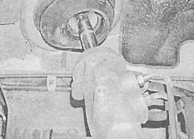
B.
24. Remove the steering gear, lower suspension arms and anti-roll bar (see Removal and installation of the front anti-roll bar, Removal, refurbishment and installation of the lower arm of the front suspension and Removal and installation of the steering mechanism). If necessary, rubber supports can be replaced, but only in pairs (e.g. right and left together). Squeezing out the supports can be done using a long threaded rod, a pair of nuts with washers and a piece of metal tube. In case of need turn out fixing bolts and remove a basic arm of the mechanism of a gear change.
Installation
Installation is carried out in the reverse order to the dismantling of the components.
1. Make sure that the mounting marks applied during dismantling are correctly aligned, tighten all fasteners with the required force. Try not to allow the rubber bushing to move when the steering input shaft is seated in it - if necessary, ask an assistant to hold the upper section of the bushing from the passenger compartment and firmly snap the lower section into the receiving hole.
Visitor comments