
Cleaning
1. Remove all externally mounted components and sensors from the unit.
2. Leaning a blunt drift against the edge of the squeeze plug, turn it in its seat at 90°. After all the plugs are deployed, it will be quite simple to remove them from the engine with tongs.
3. Scrape off all traces of the old gasket material from the mating surface of the block - try not to leave scratches and scuffs.
4. Turn out all carving plugs of oil galleries. The plugs can be very tight, to the point that they have to be drilled out and then threaded in the block. Plugs must be replaced during reassembly.
5. On diesel engines remove the piston oil nozzles. On engines 1.7 l the atomizers are pressed into the block and their removal can only be done using a special Opel tool, on engines 2.0 l nozzles are bolted.
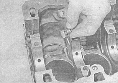
6. Remove the covers of all main bearings from the block and remove the liners of the latter from their beds. Immediately mark the removed liners with adhesive tape for belonging to your bearing and bed in it (block or cover), then set them aside.
7. In case of severe external contamination of the engine, it should be delivered to a car service workshop for steam or heat treatment.
8. After returning the block from the workshop, carefully clean all oil holes and galleries again - special cylindrical brushes of a special shape are available for this purpose (ask at car accessories stores). Flush the cavities and channels with warm water - continue flushing until clear water begins to flow from the opposite side of the block. Dry the block thoroughly, then lightly coat all machined surfaces with light oil to protect them from corrosion. If you have access to a compressed air source, use it to speed up the drying process of the block and blow out hard-to-reach cavities and channels.
Remember to wear protective goggles when working with compressed air!
9. If the unit is heavily soiled or slagged, use a brush cleaning with hot water and soap. You should not try to save time by neglecting to thoroughly clean the unit. Regardless of the method chosen, follow the thoroughness of cleaning hard-to-reach cavities, channels and holes. Finally, dry the block and lubricate the machined surfaces with thin oil to protect them from corrosion.
10. Drive all threaded holes in the block with a tap of the appropriate size to ensure that the torque wrench indicator readings correspond to the actual tightening forces developed during engine assembly. If possible, then blow out the tapped holes with compressed air, removing all small debris and chips from them. After finishing the holes, walk along the threaded part of the bolts securing the bearing caps and cylinder head.
11. Reinstall the main bearing caps by hand-tightening their fasteners.
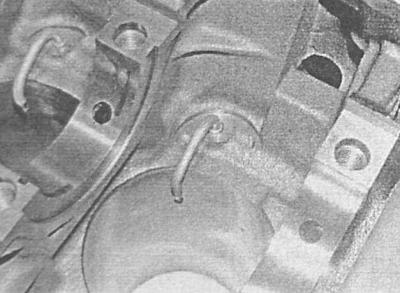
12. Lubricate the sealing surfaces of the new squeeze plugs with Permatex No 1 sealant and install them in their regular places in the block. Make sure that the corks fit perpendicularly - it would be best to use a special cylindrical mandrel, however, it can be replaced by a socket head of a suitable size, which should rest only on the inside of the end surface of the cork (not in the groove!).
13. Lubricate the threads of the new oil gallery plugs with Permatex No 2 non-hardening sealant (alternatively wrap them with fum tape). Screw the plugs into their regular places and tighten as tightly as possible.
14. On diesel engines, press in/bolt the piston oil nozzles into place.
2. If you are not going to assemble the motor immediately, place the unit in a large plastic bag to protect it from contamination.
Examination
1. The block must be thoroughly cleaned beforehand (see Removing the crankshaft).
2. Perform an external inspection of the unit for signs of corrosion, cracks and other damage. Check the condition of the threaded holes. It would also be reasonable to test the block for hidden cracks in a car service workshop using special diagnostic equipment. If defects are found, the unit must be repaired or replaced.
3. Check up a condition of mirrors of cylinders.
4. Estimate the values of the existing taper and ovality of the cylinders:
- Measure the diameter of each of the cylinders in the top (directly below the step wear boundary), central and lower sections in a plane parallel to the axis of the crankshaft;
- Now measure the diameters at the same three levels, but in a plane perpendicular to the axis of the block;
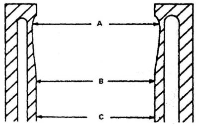
A - Under the boundary of stepped wear
B - in the middle
C - at the bottom
- The value of the taper of the cylinder determines the difference between the results of measurements in the upper and lower sections. ovality (in this section of the cylinder) called the difference in diameters measured in parallel and perpendicular to the axis of the crankshaft planes.
5. Compare test results with requirements (see Specifications). Proceeding in the manner described, check each cylinder one by one.
Keep in mind that there are several groups of standard cylinder diameters allowing different manufacturing tolerances. The size group marking is usually applied to the upper cut of the cylinder block.
6. If noticeable defects are detected or the measurement results deviate from the regulatory requirements, the cylinder block is subject to restorative machining in a car service workshop. If the cylinders were bored during the reconditioning, the engine must be equipped with new overhaul pistons (in excess) size.
oversize pistons (in excess of 0.5 mm) produced for all engines except 1.7L DOHC engines (petrol and diesel).
7. If the state of the mirrors of the cylinders during the inspection was found to be satisfactory, while at the same time complying with the regulatory requirements for the shape of the cylinders and the clearances of the pistons in them (see Checking the condition of the components of the connecting rod and piston group), there is no need to turn the cylinders - it will be enough just to honing their mirrors (see Honing cylinder mirrors).
8. Check the flatness of the surface of the block mating with the head - the check is carried out in a manner similar to that described for the mating surfaces of the cylinder head (see Cleaning and checking the condition of the cylinder head). Compare the measurement result with the requirements (see Specifications), if necessary, give the block to the groove.
Visitor comments