
It is recommended to replace the main bearing shells regardless of their condition.
1. Installation of the crankshaft is the first step in the actual assembly of the engine. It is understood that at this stage the crankshaft and engine block have already been properly cleaned, checked and subjected to the necessary refurbishment.
2. Turn the engine upside down.
3. Give fixing bolts, remove covers of radical bearings and lay them out on a workbench in the order of installation on the engine.
4. If you have not already done this, remove the old main bearing shells from your beds in the block and covers. Wipe the beds with a clean, lint-free cloth - they should be immaculately clean.
Checking the operating clearances of main bearings
Avoid touching the new bearing surfaces with bare hands to avoid unwanted contact of the bearings with traces of oil and chemicals that are always present on the fingers.
1. Wipe the backs of the new main bearing shells and place the oil grooved halves into their beds in the block (if old liners are used, make sure that they fit strictly in their original places). Insert the rest of the shell halves into the corresponding bearing caps. Make sure that the tongues of the liners enter the reciprocal landing grooves in the beds of the block and covers. The oil holes in the block must be correctly aligned with the holes in the liners.
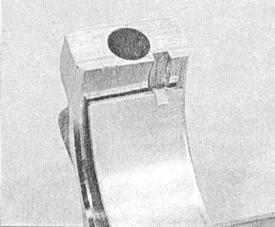
Under no circumstances should you attempt to hammer an unfitted liner into your bed with a hammer. Do not lubricate the bearings at this stage!
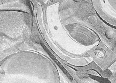
2. Remember that the combined liner equipped with thrust half rings fits into the upper bed of the third main bearing on all engines, except for the 1.7 l DOHC diesel engine, where the second bearing is thrust, and in the latter case, the half rings are supplied as separate components and must fit into special cutouts in the bed bearing with oil drain grooves outward.
3. Wipe the surfaces of the bearings in the block and the crankshaft main journals with a clean, lint-free rag.
4. Check the patency of the shaft oil holes, clean them if necessary. Any foreign particles contained in the oil paths will inevitably end up in the bearings.
5. Carefully wiped crankshaft carefully place in the main bearings of the block (do not use any lubricant).
6. Before finally installing the shaft, it is necessary to check the operating clearances in its main bearings.
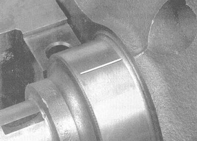
7. Cut the calibrated plastic wire from the Plastigage measuring kit into lengths slightly shorter than the width of the bushings, and lay one piece of wire along each of the main shaft journals, parallel to their axis.
8. Wipe the surfaces of the liners in the covers and install the latter in their regular places (make sure the orientation of the label is correct). Try not to move the pieces of calibrated wire laid along the necks of the shaft. Lightly oil the threads of the mounting bolts and screw them in, fixing the covers.
9. Working in a spiral from the center outward, tighten the cover bolts in three stages to the required torque (see Specifications), — do not allow the shaft to turn while tightening the fasteners!
10. Turn out bolts and carefully remove covers of radical bearings. Place the removed covers in the order in which they are placed on the engine. Take care not to damage the flattened gauge wire and do not turn the shaft. If any of the covers cannot be removed, gently tap it with a soft-faced hammer to loosen it.
11. Using the width of the flattened threads, measured on the scale printed on the packaging of the Plastigage set, determine the operating clearances of the bearings. Compare measurement results with requirements (see Specifications).
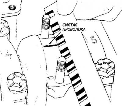
12. If the clearance is out of range, the wrong size bushings may have been installed (see Checking the condition of the main and connecting rod bearings of the crankshaft). Before looking for new liners, make sure that no foreign particles have fallen under the ones inserted at this stage. If the calibrated wire is flattened at one end more than at the other, this indicates the presence of a neck taper (see Checking the condition of the crankshaft).
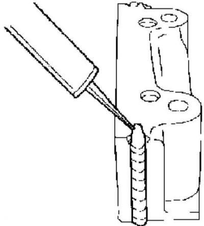
13. Carefully remove the flattened gauge wire from the necks, scraping off all traces of it with some tool that is not very strong (like the edge of an old credit card). In extreme cases, you can use your own fingernail - the main thing is that there are no scratches or scratches on the surface of the necks / liners.
Final installation of the crankshaft
1. Carefully remove the crankshaft from the engine.
2. Wipe the surfaces of the bearings in the block and evenly lubricate them with a thin layer of molybdenum or motor assembly grease. Don't forget to lubricate the thrust surfaces as well.
Try not to let grease get on the backs of the liners!
3. Make sure the crankshaft journals are absolutely clean, then lubricate (the same lubricant or clean engine oil) trunnion surfaces in contact with seals. Lay the shaft in its regular place. Wipe and lubricate the liners in the bearing caps. Make sure that the thrust washers are placed in the bed of the corresponding bearings in the block (see above Checking the operating clearances of main bearings, item 2).
4. Install the bearing caps on the motor. On all engines except diesel 1.7 l DOHC, the covers of the 1st and 4th bearings are installed first (the first is the bearing closest to the timing drive), - make sure that the markings on the covers are readable when looking at the engine from behind. Lateral grooves in the cover of the 5th (rear) bearing must be filled with sealant type no. 90485251 before installation diesel engines 1.7 l DOHC same order (without fifth cover), however, the mating surfaces of the first cover should be lightly greased with sealant before installation, the arrows stamped on the covers should point towards the timing drive.
5. Lightly lubricate the threaded portion and bottom surfaces of the mounting bolt heads with clean engine oil, then screw in and hand-tighten the bolts.
6. Working diagonally from the center outward, tighten all bolts evenly to the first stage torque, then tighten them in the same order to the corners of stages 2 and 3 (see Specifications), - use a goniometer nozzle, or apply reference marks with paint or a marker. Having reached the bolts, fill a little more sealant into the grooves of the rear cover until it begins to squeeze out of them - wipe the excess with a clean rag.
7. Tap the ends of the shaft pins with a hammer through a brass or lead drift to align the thrust surfaces and shrink the shaft before finally tightening the fasteners.
8. Rotate the crankshaft several times by hand, checking for freedom of rotation.
9. Finally, using a blade-type feeler gauge or dial gauge, determine the shaft end play (see Removing the crankshaft). If the thrust surfaces of the shaft are not worn or damaged, and the bearings are replaced with new ones, the amount of play should not be outside the allowable range.
10. Install the connecting rod and piston assemblies (see Installing connecting rod and piston assemblies and checking the working clearances in the connecting rod bearings of the crankshaft).
11. With the appropriate configuration, fit a new guide bushing of the input shaft of the gearbox into the rear crankshaft trunnion.
12. On diesel engines 1.7 l DOHC replace the front oil seal, make sure that the mating surfaces of its body and cylinder block are absolutely clean and dry. Lubricate the mating surfaces with sealant, check that the guide bushings are in place and press the stuffing box body against the block. After lubricating the threaded part of the mounting bolts with sealant, screw them into their holes and tighten with the required force. Install the rear seal.
13. On other engines installation of new crankshaft oil seals is carried out in accordance with the instructions set forth in the relevant sections (see Procedures for repairing SOHC gasoline engines without removing them from the vehicle, In-Vehicle DOHC Gasoline Engine Repair Procedures or Repair procedures for diesel engines 1.7 l and 2.0 l without removing them from the car).
14. With the appropriate configuration, install a cast bridge ligament on the main bearing caps, screw in and tighten the bolts of its fastening with the required force.
15. Further assembly of the engine is carried out in accordance with the instructions given in the relevant sections (see Procedures for repairing SOHC gasoline engines without removing them from the vehicle, In-Vehicle DOHC Gasoline Engine Repair Procedures or Repair procedures for diesel engines 1.7 l and 2.0 l without removing them from the car).
Visitor comments