
Removal of a cranked shaft is possible only from the engine taken out from the car. Assumes Flywheel/Drive Plate, Crankshaft Pulley, Timing Belt/Chains with Timing/Sprockets, Sump, Oil Pickup, Oil Pump, Main Bearing Cap Bridge (depending on configuration) and connecting rod and piston groups have already been dismantled (see part Procedures for repairing SOHC gasoline engines without removing them from the vehicle, In-Vehicle DOHC Gasoline Engine Repair Procedures or Procedures for repairing diesel engines without removing them from the vehicle).
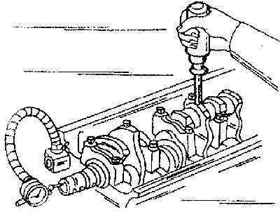
1. Before proceeding with the extraction of the crankshaft from the engine, measure the value of its axial play. Fix the dial-type gauge on the block coaxially to the crankshaft, resting its plunger against the cheek of one of the cranks or against the end of the shaft trunnion
Measuring the value of the axial play of the crankshaft using a plunger-type dial gauge
2. Push the crankshaft all the way back and reset the instrument indicator. Now push the shaft in the opposite direction and read the meter reading. The value of the shaft free play in the longitudinal direction is its axial play. Compare the measurement result with the requirements of the Specifications in Chapter Engines. If the backlash exceeds the maximum allowable value, check the thrust surfaces of the shaft for signs of excessive wear. If there are no obvious signs of wear, installing new thrust washers usually corrects the situation.
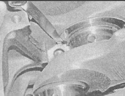
3. If you do not have a dial gauge on hand, you can use a conventional blade-type probe. Carefully slide the shaft all the way forward along the engine, then determine the amount of the resulting gap between the crank web and the semi-ring of the thrust combined insert of the third main bearing, firmly planting a blade of the appropriate thickness into it (I) probe
Alternatively, shaft end play can be measured with a blade-type feeler gauge (see paragraph text)
4. In a diagonal order, in several steps (1/4 turn per approach) Loosen the main bearing cap bolts enough to allow them to be turned out by hand. Mark the crankshaft main bearing caps with an identification mark as needed (use a punch or marker).
On most engines, all bearing caps are marked in production from 1 to 5 in ascending order from the timing drive side.
5. Gently tap the bearing caps with a soft-faced hammer and remove them from the engine block. If necessary, use the bolts as levers. Make sure that when removing the covers, the main bearing shells inserted in them are not lost.
6. Carefully remove the crankshaft from the engine - due to the significant weight of the assembly, it would be wise to enlist the help of an assistant. Make sure that the main bearing shells remain in their beds in the block and covers. Install the covers in their regular places on the block, and hand-tighten the mounting bolts.
Visitor comments