
Attention! The manufacturer recommends changing the connecting rod bearings every time the engine is disassembled, regardless of their condition.
1. Spare parts are supplied as standard connecting rod bearings of various size groups, as well as repair ones. Bearings are selected according to the measured diameter of the connecting rod journal.
Checking clearances in main bearings
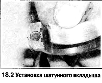
2. Insert the shells into place, making sure that the tabs on the bearing shells fit into the grooves in the connecting rod and in the connecting rod cap (see photo). If the clearance check will be performed with old liners, then insert these liners in their original places. The clearance in the connecting rod bearings can be checked in two ways.
3. When determining the gap in the first way, assemble the covers with connecting rods and connecting rod bearings, making sure that the relative orientation of these parts is correct. Tighten the cap nuts to the specified torque and measure the inside diameter of each assembled pair of shells. Clearance is defined as the difference between the inside diameter of the assembled connecting rod bearings and the diameter of the connecting rod journal.
4. The second way (more accurate) consists in the use of a plastic gauge wire.
5. Install the connecting rod bearings, orienting them correctly. Place a piece of gauge wire on each connecting rod journal of the crankshaft.
6. Clean the surfaces of the connecting rod bearings and install the connecting rods on the corresponding crankshaft journals. Install the connecting rod bearing caps. Tighten the nuts of the covers When tightening, changing the position of the wire is not allowed, and the crankshaft is not allowed to turn. Remove the connecting rod caps without allowing the crankshaft to rotate or the gauge wire to move. Compare the flattened wire width to the scale on the package and determine the clearance in the main bearings.
7. If the gap differs from the standard, then the reason may be the wrong selection of connecting rod bearings (or their increased wear if used liners were checked). Before concluding that the bearings need to be replaced, make sure that there is no dirt or oil between the surfaces of the caps or connecting rods and the bearing when measured. If the width of the flattened wire from one edge is greater, then this indicates a tapered crankpin.
8. If there is a gap when installing new liners, then you should seek advice from a car service, as it may be necessary to regrind the connecting rod journals of the crankshaft and replace the liners with repair ones.
Installing the connecting rod and piston group
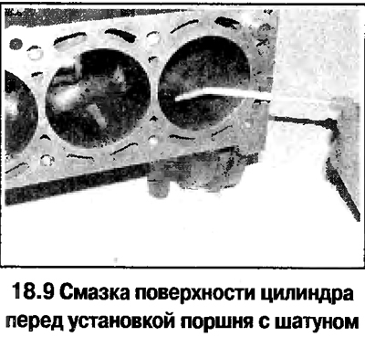
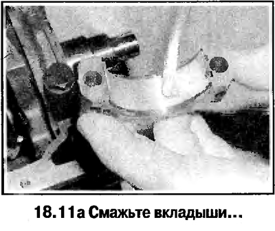
9. Make sure the connecting rod bearings are installed correctly. If new bearings are installed, wash them in kerosene. Wipe the connecting rods and bearings dry. Lubricate the cylinders, pistons and rings, then lay out the pistons and connecting rods in the order in which these parts will be installed on the engine (see photo).
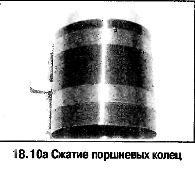
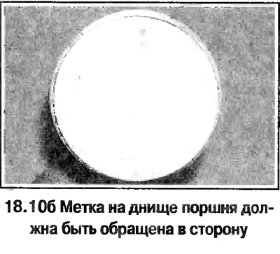
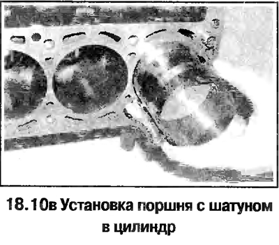
10. Start the assembly from the 1st cylinder. Make sure the piston rings are properly aligned (see above) and squeeze the rings with a special tool (see photo). Insert the piston and connecting rod assembly into the first cylinder. Orient the piston so that the mark on the piston crown (in the form of an arrow or a dash) facing towards the front of the engine. Tap the piston lightly with a hammer handle or a wooden block so that the piston enters the cylinder and the piston bottom is level with the split plane of the cylinder block (see photo).
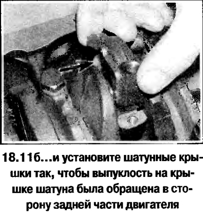
11. Make sure the connecting rod bearings are installed correctly and generously lubricate the bearings and the crankshaft journal. Being careful not to damage the cylinder surface, tighten the connecting rod to the crankshaft journal. Put on the connecting rod cap with insert and tighten the nuts by hand. Note that the bulge on the connecting rod cap must face towards the rear of the engine (flywheel). Screw on the bolts and pull by hand.
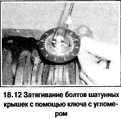
12. Tighten the connecting rod cap bolts in the order specified in the Technical data (see photo).
13. On 2.0L engines, install a balancing mechanism (or lid frame).
14. Install a new rear oil seal, flywheel, cylinder head, oil pump, oil deflector, sump and camshaft belt.
15. Establish on the engine the removed knots and units and establish the engine on the car.
Visitor comments