
Attention! It is recommended to install new piston rings and connecting rod bearings, regardless of the condition of the previous ones.
Earbud selection
1. Various grades of connecting rod bearings are available for sale. The required bearing size can be determined by measuring the crankshaft journals (see Chapter 13).
Checking the operating clearance of the connecting rod bearing
2. Clean the backs of the shells and bearing surfaces in the connecting rods and caps.
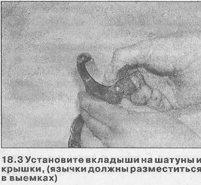
3. Insert the liners into place in the connecting rods and caps. Make sure the mounting tabs fit into the slots (see illustration). If the old liners are used during the check, install them strictly in the same place. The gap can be determined in one of two ways.
4. First method (internal micrometers or calipers required) - Install the covers on the connecting rods with liners in the working position. Tighten the cap bolts to the specified torque and measure the diameter of the hole formed by each pair of bushings (bearing inner diameter). Measure the diameter of each crankshaft journal and subtract it from the inside diameter of the bearing. The result obtained is equal to the working clearance of the connecting rod bearing.
5. Second (and more accurate) method consists in using a special Plastigauge tool as described in Chapter 17, paragraphs 5-14.
Installation of piston/connecting rod assemblies
6. Check that the liners are correctly installed as described above in steps 2 and 3. If new liners are being installed, remove the protective grease from them.
7. Lubricate the cylinders, pistons and piston rings, then place each piston/connecting rod assembly in its proper position.
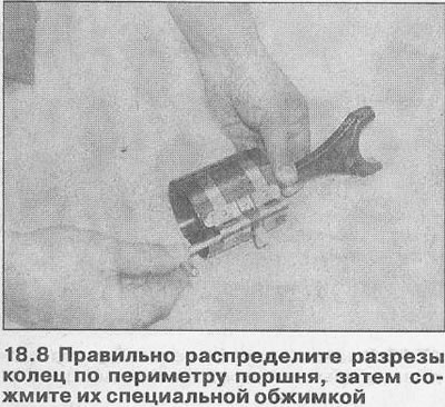
8. Starting with assembly #1, position the piston rings as described in Chapter 16, then compress them with a special swage (see illustration).
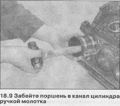
9. Insert the piston/connecting rod assembly into the top of #1 cylinder, making sure the arrow on the piston head points toward the front end of the engine. Using a block or hammer handle, carefully hammer the assembly into the cylinder until the piston head is flush with the surface of the block (see illustration).
10. Being careful not to damage the cylinder walls, generously lubricate the crankshaft journal and both bearing shells, then insert the piston/connecting rod assembly into the cylinder bore onto the crankshaft journal.
11. Track, that contact surfaces of a rod and a cover were pure and dry.
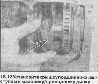
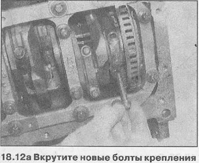
12. Install the connecting rod bearing cover, correctly orienting it according to the marks (the tab on the base of the bearing cap must face the flywheel/drive plate), then screw in new mounting bolts (see illustrations).
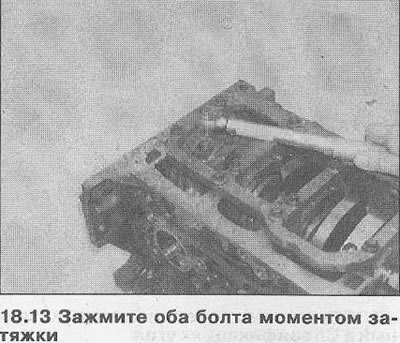
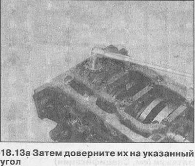
13. Tighten both bolts of fastening of a cover the moment of an inhaling (see the specifications of the relevant section), then turn them to the specified angle (see illustrations).
14. Install the remaining piston/rod assemblies in the same manner.
15. Check that the crankshaft rotates freely.
16. On 4-cylinder engines, do the following:
- A) Install the crankshaft balancer assembly as described in Part A.
- b) On all engines, install the oil pump downpipe and sump, then install the cylinder head as described in Part B.
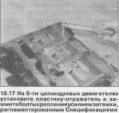
17. On 6-cylinder engines, install the reflector plate on the base of the clamping frame of the main bearing caps, and tighten the fastening bolts with a tightening torque regulated specifications (see illustration). Acting as described in Parts In This Section, install the sump, then install the cylinder heads.
Visitor comments