
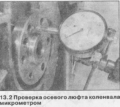
2. Check the crankshaft axial clearance with a micrometer (see illustration). Push the crankshaft all the way to one side, and then set the micrometer to zero. Extend the crankshaft completely to the other side and check the end play. The result can be compared with that shown in Specifications and determine if new thrust washers are required.
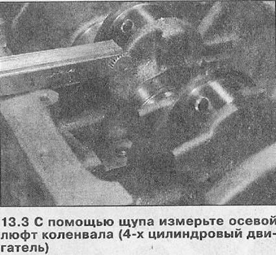
3. If there is no micrometer, feelers can be used (see illustration). First push the crankshaft toward the flywheel/drive plate, then insert a feeler gauge between the crankshaft journal counterweight and the thrust washer, which on 4 cylinder engines is included in main bearing shell #3, and on 6 cylinder engines it is included in main bearing shell #3. 4.
Inspection
4. Clean the crankshaft using kerosene or a suitable solvent and dry it with compressed air if possible.
5. Check main and connecting rod journals for uneven wear, scratches, corrosion, and cracks.
6. When the connecting rod bearing is worn, a metallic tapping sound is clearly audible during engine operation (especially noticeable at low revs), and this is accompanied by some loss of oil pressure.
7. When the main bearing is worn, there is a strong vibration and roar of the engine, gradually increasing with increasing engine speed, this is also accompanied by a loss of oil pressure.
8. Check the smoothness of the bearing journal surface by running your finger over it. When you feel any roughness (the liner will be worn out), the crankshaft needs to be reground (if it is possible) or replace.
9. If the crankshaft has been reground, check that there are no burrs around the crankshaft oil holes (holes are usually beveled). Remove them with a fine file or scraper and clean the oil holes thoroughly as described above.
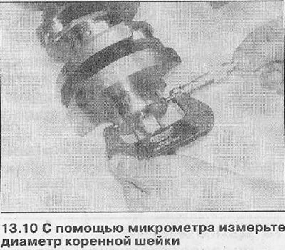
10. Using a micrometer, measure the diameter of the journals of the main and connecting rod bearings, and compare the results with the Specifications (see illustration). By measuring the diameter at several points along the circumference of each neck, it is possible to determine its ovality. By measuring the diameter of the neck at each edge near the counterweights, the taper of the neck can be determined. Compare the results obtained with the data given in the Specifications. If there are still colored marks on the crankshaft, the size of the bearing neck can be determined from them.
11. Check the oil seal contact surfaces at each end of the crankshaft for damage and signs of wear. If there is a deep groove on the surface of the crankshaft, consult an engine overhaul specialist about the possibility of rebuilding the crankshaft; if repair is not possible, a new crankshaft will be required.
12. Install the crankshaft into the V-blocks, place the micrometer on top of the #1 crankshaft main journal. Set the micrometer to zero, then slowly rotate the crankshaft two full turns, noting the journal runout. Repeat the procedure on the remaining root necks. If the difference between the beats of any two journals exceeds the limit value given in the Specifications, the crankshaft must be replaced.
13. For all engines, Opel produces main and connecting rod bearings oversized. If the crankshaft journals have not yet been re-sharpened, then it is possible to restore it, and when installing, use liners of repair sizes. On sale there are radical repair liners in sizes 0.25 and 0.50 mm, and connecting rod repair liners in sizes 0.25 and 0.50 mm (for 6 cylinder engines) and dimensions 0.25 mm (for 4 cylinder engines).
Visitor comments