


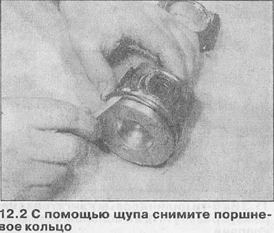
2. Carefully loosen the rings and remove them from the piston head (see illustration). Use two or three old feeler gauges to prevent the rings from jumping into the now empty grooves. Be careful not to scratch the piston with the ends of the rings. Note that the third (oil scraper) the ring consists of a spacer gasket and two parts. Store the ring sets together with the piston.
3. Clean off the main carbon deposits from the piston head. Then clean it with a wire brush or fine sandpaper. The piston identification marks should now be visible.
4. Remove carbon deposits from the piston ring grooves using a piece of an old ring (break the ring in half, working carefully so as not to cut your fingers). Be careful not to remove any metal along with the carbon deposits and not to scratch the walls of the grooves.
5. After removing the carbon deposits, clean the piston/connecting rod assembly with kerosene or a suitable solvent and dry it thoroughly. Make sure that the oil return holes in the ring grooves are not clogged.
6. If the pistons and cylinder walls are not damaged or worn and if the cylinder block does not require regrinding (see Chapter 11), check the pistons as follows.
7. Carefully inspect each piston for cracks in the skirt, around the piston pin holes and between the ring grooves.
8. Inspect the piston skirt for damage and the piston crown for pinholes or burns. If the skirt is scratched or nicked, or the piston crown is gouged or burned, the engine may have overheated and/or misfired (the fuel mixture ratio or injection/ignition timing were incorrectly adjusted). Check the cooling and lubrication systems carefully. Burnt spots on the piston sides indicate that a gas leak has occurred. If any of the above damage is detected, identify the causes and eliminate them, otherwise the damage will occur again. The cause may be an air intake leak, improper fuel/air mixture adjustment, incorrect ignition timing, or a defective injector.
9. Piston corrosion indicates that coolant has leaked into the combustion chamber and/or crankcase. Find the cause of the leak and fix it.
10. Measure the piston diameter perpendicular to the piston pin axis; compare the results with Specifications at the beginning of this Section. Please note that there are different size groups of pistons of nominal diameter, taking into account permissible manufacturing deviations; the size group marking is imprinted on the piston head.
11. To determine the clearance between the piston and the cylinder wall, measure the cylinder bore diameter (see Chapter 11) and the diameter of the piston skirt (the difference between the obtained measurements will be the gap), or insert the piston into the corresponding cylinder bore, then determine the clearance by inserting a feeler gauge between the piston and the cylinder wall. The feeler gauge must be installed between the piston and the bore walls on one of the thrust surfaces at the base of the cylinder. If the clearance is greater than the permissible value, a new piston is required. If the piston gets stuck at the bottom of the cylinder and is released at the top, the cylinder is tapered. If the feeler gauge gets stuck in some places when moving around the perimeter of the piston in the cylinder bore, the cylinder is oval.
12. Repeat this procedure with the remaining pistons and cylinders. Worn pistons should be replaced.
13. Carefully inspect each connecting rod for damage: cracks around the bearing of the lower and upper heads. Check that the connecting rod is not bent or distorted. A detailed inspection of the connecting rod assemblies can only be done by an Opel dealer or an engine repair specialist.
14. On 2.0 and 2.5 L engines, the piston pins are pressed into the connecting rod upper end bushing. Therefore, piston and/or connecting rod replacement should be entrusted to an Opel dealer or engine repair specialist who has the necessary tools to remove and install the piston pins. If new pistons are to be installed, make sure that they are the correct size group for each cylinder (see Chapter 12).
Caution! Piston/connecting rod assemblies must not be separated. If any component requires replacement, the complete assembly must be replaced. Do not install a new piston on an old connecting rod or vice versa.
15. On 3.0L engines the piston pins are of the floating type, secured by two retaining rings. On these engines the pistons can be separated from the connecting rods as follows.
16. Using a small flat-head screwdriver, remove the snap rings and push out the piston pin. Make marks on the piston and connecting rod to ensure proper assembly. Discard the snap rings and use new ones for assembly.
17. Inspect the piston pin and connecting rod upper head bushing for damage and signs of wear. If worn, replace the pin and connecting rod.
18. The connecting rods themselves should not need replacing unless the engine has seized or suffered other mechanical damage. Visually inspect the connecting rods, and if they appear warped, have an engine rebuilder perform a detailed inspection.
Information taken from the website OpelBook.ru
19. Inspect all components, purchase new parts. New pistons will be supplied with pins and retaining rings. Retaining rings can also be purchased separately.
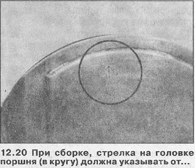
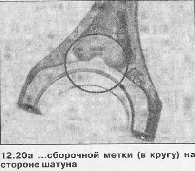
20. Assemble the piston and connecting rod so that the arrow on the piston head points away from the mark that is cast on one side of the lower connecting rod head (see illustrations).
21. Apply a small amount of clean engine oil to the piston pin. Insert it through the small end of the connecting rod into the piston. Then secure the pin with two new snap rings, correctly positioning them in the grooves.
Visitor comments