
Connecting rod, pin and piston
Select pistons according to the cylinder size category stamped on the block or based on the repair size obtained after reboring the cylinders.
Check the tolerance of parallelism and misalignment of the axes of the holes of the connecting rod heads, which should not exceed 0.025 mm over a length of 125.4 mm, and straighten the connecting rods if necessary.
Press the piston pin out of the connecting rod on a press without heating using a mandrel. The piston and piston pin must be replaced.
Place the connecting rod in an electric furnace or on a heating plate with a power of 1500-2000 W, heat it to a temperature of 280°C, controlling the heating temperature with a thermochromic pencil.
Place the piston pin on the assembly tool and lubricate with oil. Remove the connecting rod from the oven and clamp quickly in a vise. Place the piston on the upper head of the connecting rod, aligning the pin holes. Push the piston pin on the mounting tool into the connecting rod bore until the shoulder of the mounting tool rests on the piston skirt.
Note. To correctly connect the pin to the connecting rod, press the pin as soon as possible, since the connecting rod cools quickly and after cooling it will not be possible to change the position of the pin without deforming the piston.
When connecting a new piston to a connecting rod, maintain the nominal mounting dimensions specified in subsection «Design and specifications».
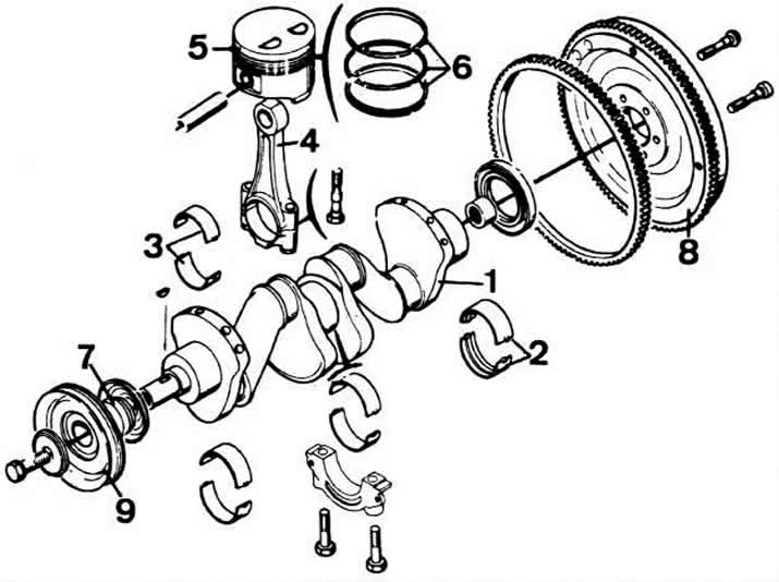
Details of the crank mechanism:
1 - crankshaft;
2 - liners of main bearings;
3 - liners of connecting rod bearings;
4 - connecting rod;
5 - piston;
6 - piston rings;
7 - crankshaft sprocket;
8 - flywheel;
9 - crankshaft pulley.
Visitor comments