
Removing
1. Remove the engine (see relevant chapter) and install it on the stand.
2. Remove the vibration damping block (see relevant chapter).
3. Remove the cylinder head (see relevant chapter).
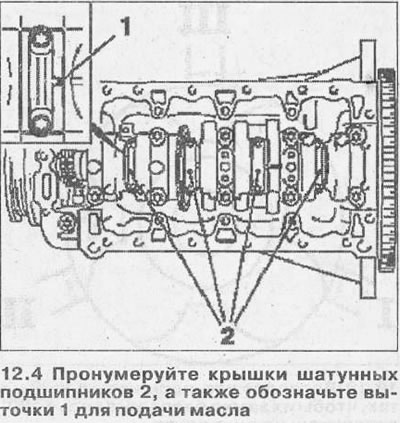
4. Number the connecting rod bearing caps 2, and also mark the undercuts 1 for oil supply (see illustration).
5. Unscrew bolts of fastening and remove covers of rods.
6. Remove carbon deposits from the top of the cylinders and remove the appropriate piston along with the connecting rod.
7. Clean and inspect all parts. If necessary, replace them with new ones.
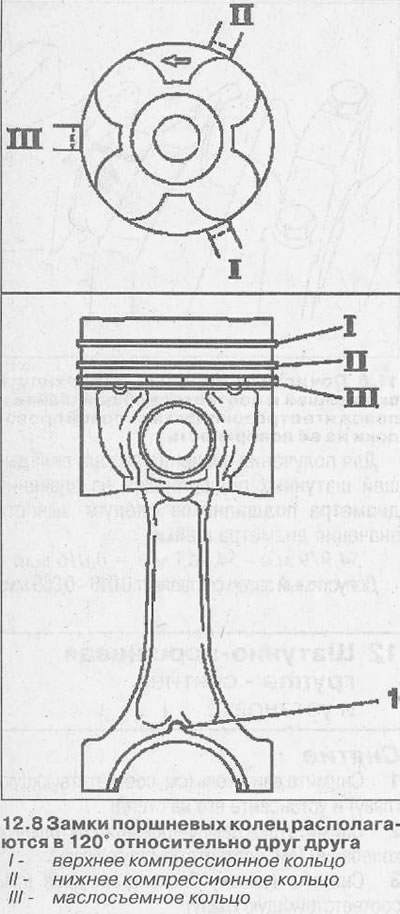
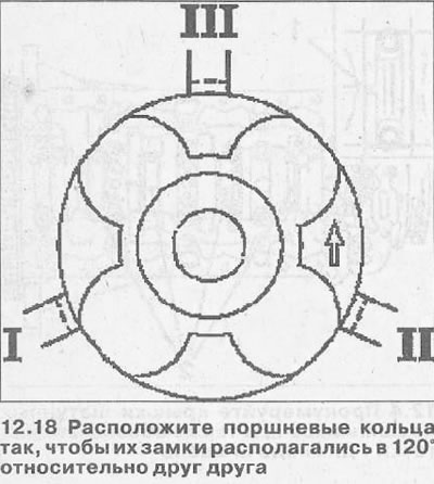
8. Designate position of piston rings. Piston ring locks are located at 120°relative to each other (see illustration).
9. Compress the rings with a special tool, having previously lubricated them with engine oil, and insert the piston with the connecting rod into the cylinder bore.
Attention! Observe the installation position of the piston, focusing on the arrow on the piston crown and oil outlet hole 1 on the connecting rod (see illustration 12.8).
10. Tap the piston with a hammer handle until it is fully seated in the cylinder bore.
11. Install the connecting rod bearing caps, following the marks made before removal, screw in new fastening bolts and tighten them with a force of 35 NM, followed by 45°and 15°increments.
Piston rings - removal and installation
12. Remove the piston from the cylinder bore along with the connecting rod.
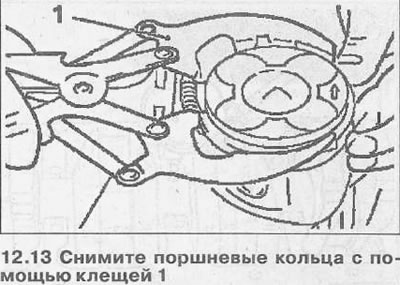
13. Remove piston rings with pliers 1 (see illustration).
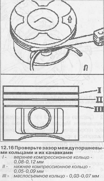
14. Clean the rings and their grooves on the piston. To clean the grooves, you can use the old ring.
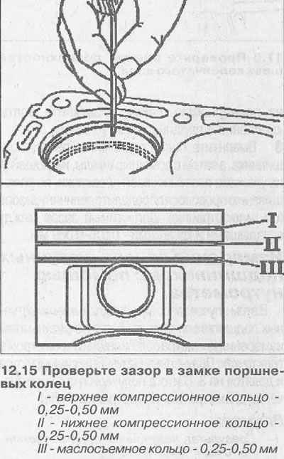
15. Check the clearance in the piston ring lock using feeler gauges by inserting the rings into the gauge (see illustration).
16. Check the gap between the piston rings and their grooves using feeler gauges (see illustration).
17. Install the piston rings in the grooves with pliers. In this case, the lower compression ring is installed so that the inscription «TOR» on it was turned up.
18. Position the piston rings so that their locks are located 120°relative to each other (see illustration).
Piston - replacement
19. Remove the piston from the cylinder bore along with the connecting rod.
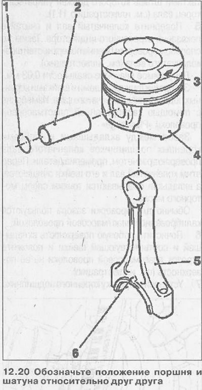
20. Before disassembling the piston and connecting rod, mark the position of the piston pin 2 in the head 5 of the connecting rod and in the piston bore 4. The connecting rod is installed in the piston so that its wall with the oil outlet hole 6 on it faces away from the arrow 3 on the piston bottom (see illustration).
21. Remove thrust ring 1 from the piston pin using needle nose pliers or other suitable tool and press out the pin (see illustration 12.20).
22. Lubricate the piston pin with engine oil and press it in by hand to the seating groove of the thrust ring.
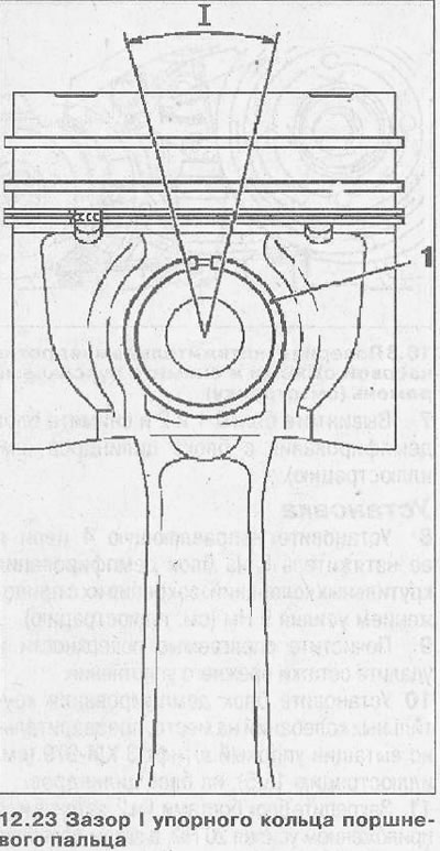
23. Stop the piston pin with a thrust ring 1 and check the gap I between the ends of the thrust ring. The clearance angle must not exceed 30° (see illustration).
Visitor comments