
OpelBook.ru
Cars AvtoVAZ Cars Mitsubishi Cars BMW Cars Mercedes Cars Nissan Cars Toyota Cars Chevrolet
English Русский
Български
Беларускі
Український
Српски
Hrvatski
Română
Polski
Slovenský
Magyar
 |  Sitemap  |  Contacts  |    


Main Astra Corsa Insignia Kadett Omega Vectra Zafira Others Articles
Omega A (1986-1993) Omega B (1993-1999) Omega B2 (1999-2003)
  • Main
  • Omega
  • Omega B2
  • Power unit
  • Diesel engines 2.0 l
  • Cylinder head — overhaul

Cylinder head — overhaul (Opel Omega B2)

            0

1. Remove the cylinder head (see the relevant chapter).

Caution! Place the removed head on wooden blocks to avoid damaging the injectors, glow plugs and valves.


2. Disconnect the exhaust manifold together with the turbocharger, the generator mounting bracket, the lower part of the intake manifold and the engine lifting eyes from the cylinder head.

Caution: Mark all camshaft bearing caps before removing them so that they can be reinstalled in their original locations during reassembly.


3. Loosen the camshaft bearing cap bolts by turning them half a turn or a full turn in a spiral motion as shown in the illustration. After loosening all the cap bolts, remove them and remove the camshaft (see illustration).
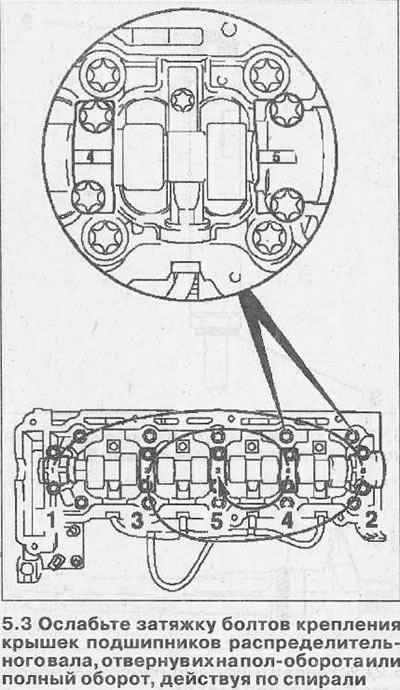
3. Loosen the camshaft bearing cap bolts by turning them half a turn or a full turn in a spiral…


Attention! Place the removed injectors, rocker arms and hydraulic tappets in the order they were removed so that they can be installed in their original places during assembly.


4. Unscrew bolt 1 of the fastening, lift the injector rail and remove it (see illustration).
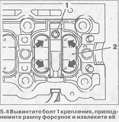
4. Unscrew bolt 1 of the fastening, lift the injector rail and remove it (see illustration).


5. Remove the rocker arms 2 of the valve drive, having previously marked their position (see illustration 5.4). The reference marks on the rocker arms in the form of arrows are located on the ends adjacent to the injector ramp.


6. Remove the sealing rings from the fuel injectors.

7. Screw the KM-931 adapter onto the fuel injectors, install the KM-328-V puller onto it, unscrew the fuel injectors and remove the heat-protective gaskets.

8. Unscrew the glow plugs using the KM-980 key.

9. Mark the valves and their mounting locations.

10. Compress the valve springs using the puller 1 KM-348 and adapter 2 KM-653-A, remove the crackers, remove the plate and springs (see illustration).
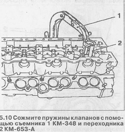
10. Compress the valve springs using the puller 1 KM-348 and adapter 2 KM-653-A, remove the…


11. Using the KM-840 puller, remove the oil deflector caps and remove the support washers of the lower (outer) valve springs.

12. Clean all parts.

13. Inspect all parts and their surfaces for damage and wear.

14. Lubricate the valves with engine oil and install them in the guides on the cylinder head, following the markings made before removal.

15. Install the lower spring support washers and oil seals 1 (see illustration).
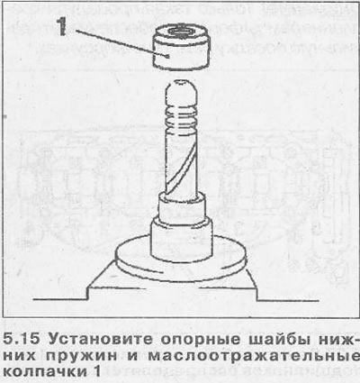
15. Install the lower spring support washers and oil seals 1 (see illustration).


16. Install the springs and their plates, compress the springs with the KM-348 puller and the KM-653-A adapter and insert the crackers.


17. Install new sealing rings 2 and 3 on the fuel injectors and apply white sealant to them (see illustration).
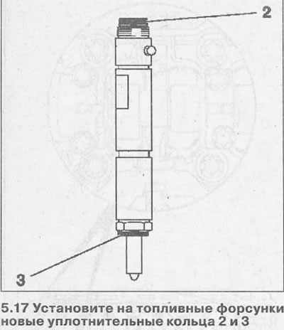
17. Install new sealing rings 2 and 3 on the fuel injectors and apply white sealant to them (see…


18. Install the fuel injectors onto the cylinder head.

19. Screw in the glow plugs, tightening them to 10 Nm.

20. Lubricate the hydraulic tappets with engine oil and install them on the cylinder head according to the markings made before removal.

21. Install a new sealing ring 1 on the injector rail and lubricate it with a thin layer of white sealant (see illustration).
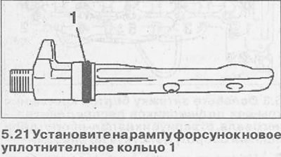
21. Install a new sealing ring 1 on the injector rail and lubricate it with a thin layer of white…


22. Install the injector rail into the cylinder head, being careful not to damage the sealing ring.

23. Secure the injector rail with a new bolt, tighten it with a wrench without a ratchet and turn it 360° (see illustration).
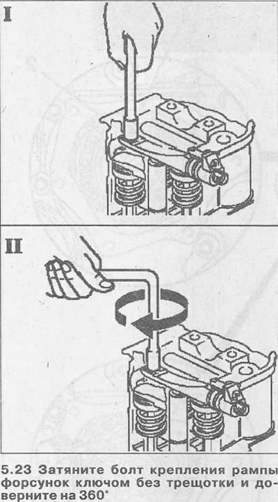


23. Secure the injector rail with a new bolt, tighten it with a wrench without a ratchet and turn…


Attention! Only this procedure for fastening the injector rail ensures the correct fit of the rail on the injectors.


24. Install the valve rocker arms into the cylinder head, following the markings made before removal.

25. Apply black sealant to the shaded areas indicated by the arrows (see illustration).
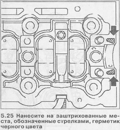
25. Apply black sealant to the shaded areas indicated by the arrows (see illustration).


26. Apply grey molybdenum grease to the mating surfaces of the rocker arms and camshaft and place the camshaft into the cylinder head.

27. Install the camshaft bearing caps, observing the markings made before removal, screw in their mounting bolts and tighten the bolts, acting in a spiral pattern (see illustration). First tighten all bolts by half a turn or a full turn, and then, maintaining the specified order, tighten them with a force of 15 Nm.
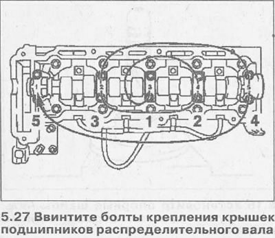


27. Install the camshaft bearing caps, observing the markings made before removal, screw in their…


28. Install the lower part of the intake manifold on the cylinder head, replacing the old sealing gasket and mounting nuts with new ones. Tightening torque of the nuts is 22 Nm.

29. Connect the upper part of the intake manifold to the lower part of the cylinder head, replacing the sealing gasket with a new one and tightening the mounting bolts with a force of 8 Nm.

30. Connect the exhaust manifold to the head, replacing the sealing gasket and mounting nuts with new ones. Tightening torque of the nuts is 22 Nm.

31. Install the generator mounting bracket, replacing its seal with a new one. The tightening torque of the bracket mounting bolts is 20 Nm.

32. Screw the engine lifting eye to the head using a torque of 20 Nm.


This article is available at russian, bulgarian, belarusian, ukrainian, serbian, croatian, romanian, polish, slovak, hungarian
Checking the article: Shapovalov Yaroslav

Share information:

Previous articles
Opel Omega B2: Diesel engines 2.0 l
Next articles

Cylinder head — removal and installation
TDC of piston of cylinder No. 1 — installation
Cylinder Head Cover — Removal and Installation
Engine — removal and installation
2.0 litre diesel engine specifications
Camshaft — Removal and Installation
Vacuum pump — removal and installation
Timing Gear Housing — Removal and Installation
Oil pump — removal and installation
Crankshaft — removal and installation
Crankshaft — checks


See similar ones from other Opel car manuals:
▶ Cylinder head — removal and installation Opel Astra F (1991-1998, petrol)
▶ Removal and installation the cylinder head Opel Corsa B (1993-2000)
▶ Cylinder head cover Opel Insignia A (2008-2017)
▶ Cylinder head specifications Opel Kadett E (1984-1995)
▶ Cylinder head — removal and installation (engine in a car) Opel Vectra A (1988-1995, petrol)
Link to this page in different formats

Visitor comments


No comments yet


How much will 50 + 44 =


Omega B2 (1999-2003) 
  • General information
  • User manual
  • Maintenance
  • Troubleshooting
  • Power unit
  • Petrol 4-cylinder
  • Petrol 6-cylinder
  • Engine overhaul
  • Diesel engines 2.0 l
  • Diesel engines 2.5 l
  • Cooling and heating
  • Injection system (gasoline)
  • Fuel system (diesel)
  • Fuel system
  • Exhaust system
  • Ignition system
  • Transmission
  • Clutch
  • Mechanical gearbox
  • Automatic gearbox
  • Main gear and shafts
  • Chassis
  • Brake system
  • Car suspension
  • Steering
  • Body
  • Body elements
  • Electrical equipment
  • Equipment and devices
  • Electrical circuits
Omega B (1993-1999) 
  • General information
  • User manual
  • Tips for the car owner
  • Maintenance (gasoline)
  • Maintenance (diesel)
  • Power unit
  • Petrol engine SOHC 2.0 l
  • Petrol engine DOHC 2.0 l
  • Petrol engines 2.5 and 3.0 l
  • Repair of gasoline engines
  • Diesel engine 2.0 l
  • Diesel engine repair 2.0 l
  • Diesel engine 2.5 l
  • Cooling and heating
  • Power system (petrol)
  • Emission reduction
  • Fuel system (diesel 2.0 l)
  • Fuel system (diesel 2.5 l)
  • Launch system
  • Ignition system
  • Transmission
  • Clutch
  • Mechanical gearbox
  • Automatic gearbox
  • Drive shafts
  • Chassis
  • Brake system
  • Wheel suspension
  • Steering
  • Body
  • Exterior
  • Interior
  • Doors and windows
  • Electrical equipment
  • Equipment and devices
  • Wiring diagrams (early)
  • Wiring diagrams (late)
Omega A (1986-1993) 
  • General information
  • User manual
  • Maintenance
  • Changes and additions
  • Troubleshooting
  • Power unit
  • Gasoline engines
  • Diesel engines
  • Cooling system
  • Fuel system (gasoline)
  • Fuel system (diesel)
  • Ignition system
  • Transmission
  • Clutch
  • Mechanical gearbox
  • Automatic gearbox
  • Cardan shaft
  • Drive shafts
  • Chassis
  • Brake system
  • Car suspension
  • Steering
  • Body
  • Exterior
  • Interior
  • Electrical equipment
  • Power devices
  • Lighting and appliances
  • Electrical circuits
OpelBook.ru © 2017–2026 · Mobile version · · Sitemap: EN BG BY UA RS HR RO PL SK HU · Feedback · Site search
Astra F, petrol · Astra G, petrol · Astra G · Astra H · Astra J, petrol · Corsa B · Corsa C, petrol · Corsa C · Insignia A · Kadett D · Kadett E · Omega A · Omega B · Omega B2 · Vectra A, petrol · Vectra A · Vectra B, petrol · Vectra B · Vectra C · Zafira A, petrol · Frontera A, petrol · Frontera B · Ascona C · Vivaro A ·
We want your visit to be comfortable 🤝! We use cookies 🍪 to make that happen.