
Removing
1. Set the piston of cylinder No. 1 to TDC by following the steps outlined in the appropriate chapter.
2. Remove tensioner 1 of the timing chain, having previously marked its mounting position (see illustration).
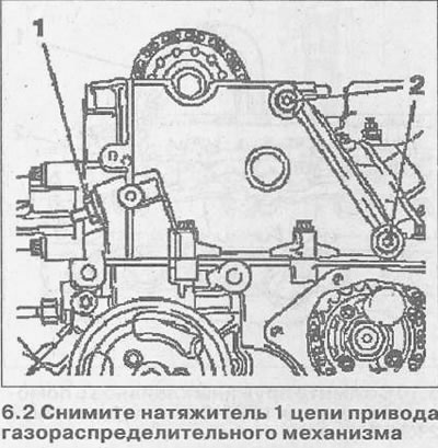
3. Heat the bolts 2 fastening the damper of the timing chain with a hair dryer, unscrew them and remove the damper (see illustration 6.2). Clean the holes for the damper mounting bolts.
4. Remove the KM-932 tool, with which the camshaft was fixed, and also remove the KM-927 thrust pin from the hole on the injection pump drive sprocket (see relevant chapter).
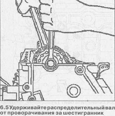
5. Remove the drive sprocket from the camshaft by unscrewing the mounting bolt. At the same time, hold the camshaft from turning by the hexagon with the second key (see illustration).
6. Remove the timing chain from the camshaft sprocket and attach it to the timing cover.
7. Mark the mounting position of the camshaft bearing caps before unscrewing and removing them.
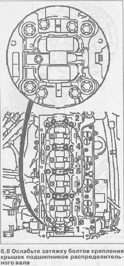
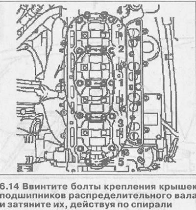
8. Loosen the camshaft bearing cap bolts by backing out a half turn or a full turn in a spiral pattern as shown in the illustration. Then unscrew the bolts in the same sequence.
Attention! If the camshaft is to be replaced, the rocker arms must also be replaced.
9. Clean sealing surfaces and remove any remaining seal.
10. Inspect the camshaft and bearing caps for wear and damage and replace if necessary.
Installation
11. Reinstall the rocker arms of the valve drive, guided by the marks. Reference marks on the rocker arms in the form of arrows are located on the ends adjacent to the injector ramp.
12. Lubricate the mating surfaces of the rocker arms and camshaft with gray molybdenum grease and lay the camshaft in the cylinder head.
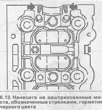
13. Apply black sealant to the shaded areas indicated by the arrows (see illustration).
14. Establish covers of bearings of a camshaft, observing the designations made before removal, screw in bolts of their fastening and tighten bolts, acting on a spiral (see illustration). Pre-tighten all bolts a half turn or a full turn, and then, maintaining the specified order, tighten them with a force of 15 Nm.
15. Put the drive chain on the camshaft sprocket and secure the sprocket to the camshaft by screwing in and hand-tightening a new mounting bolt.
Attention! The sprocket should fit snugly on the shaft.
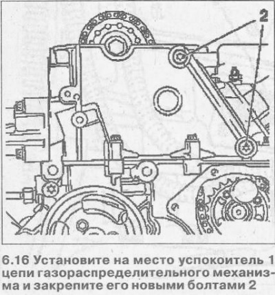
16. Reinstall the damper 1 of the timing chain and secure it. new bolts 2 (see illustration). The tightening torque for the damper bolts is 8 Nm.
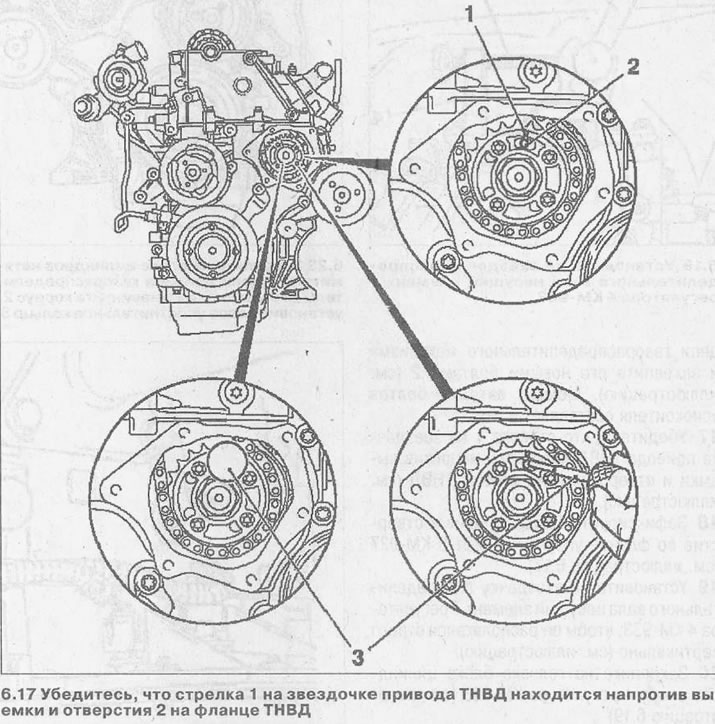
17. Make sure that the arrow 1 on the injection pump drive sprocket is opposite the notch and hole 2 on the injection pump flange (see illustration).
18. Fix the injection pump by inserting a thrust pin 3 KM-927 into the hole in the flange (see illustration 6.17).
19. Install the carrier element 1 of the regulator 4 KM-933 on the camshaft sprocket so that it is located strictly vertically (see illustration).
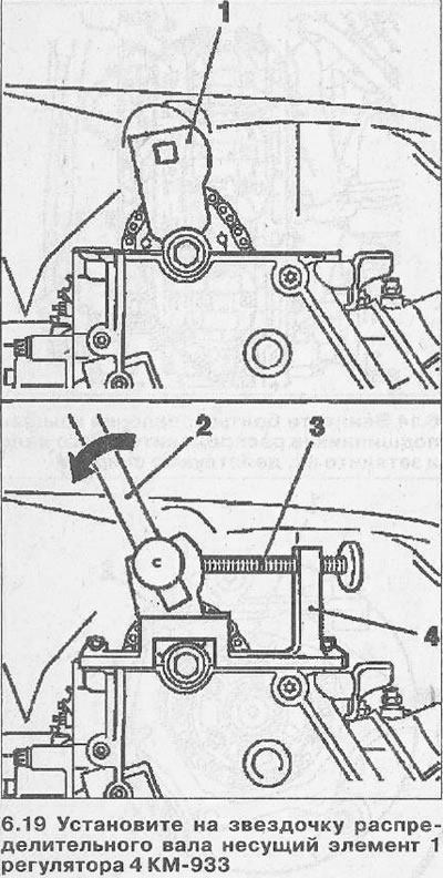
20. Fix the support 4 of the KM-933 regulator on the cylinder head (see illustration 6.19)
21. Fasten the handle 2 in the hole of the bearing element 1, pull it out in the direction of the arrow and fix the element in this position with the clamping bolt 3 (see illustration 6.19).
22. Tighten the sprocket mounting bolt on the camshaft with a force of 90 Nm, and then tighten it first by 60°and then by 30°.
23. Fix the tensioner 4 of the timing chain on the cylinder block and screw on the housing 2 by installing a new sealing ring 3 (see illustration). The tightening torque for the housing is 60 Nm.
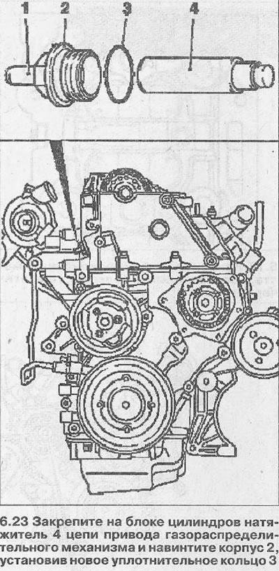
Attention! Depending on the model, the tensioner can be with a detachable pin 1 (see illustration 6.23) or without.
24. Install pin 1 by hammering it (see illustration 6.23). The finger should snap into place with a distinct click.
25. Remove the installed thrust bolts and fixtures.
26. Turn the crankshaft for the vibration damper mounting bolt on the accessory drive belt pulley two turns (720°) in the direction of rotation of the engine so that mark 3 on the pulley «TDC cylinder #1» installed at some distance from the reference mark 2 on the cover of the gas distribution mechanism (see illustration).
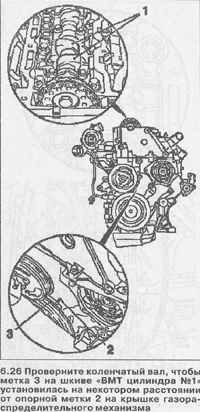
In this position, the cams 1 of the cylinder piston valve drive must be turned up (see illustration 6.26).
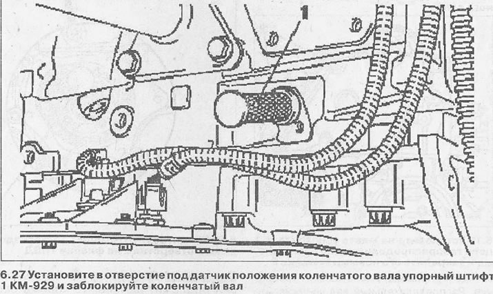
27. Install thrust pin 1 KM-929 in the hole for the crankshaft position sensor and block the crankshaft (see illustration). If necessary, turn the crankshaft slightly in the direction of engine rotation to achieve the desired seating of the thrust pin.
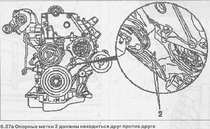
In this position of the crankshaft, reference marks 2 must be opposite each other (see illustration 6.27a).
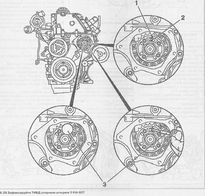
28. Fix the injection pump with a thrust pin 3 KM-927, inserting it into the hole on the flange of the drive sprocket (see illustration). Arrow 1 on the injection pump sprocket must match the notch and hole 2 on the flange (see illustration).
29. Fix the camshaft using tool 3 KM-932, fixing it on the cylinder head and inserting its thrust pin 2 into hole 1 of the camshaft flange (see illustration).
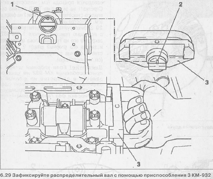
Attention! If the thrust pin 2 of the KM-932 device cannot be inserted into the hole on the flange and thus fix the camshaft, then the procedure for adjusting the valve timing should be completely repeated.
Visitor comments