OpelBook.ru
Cars AvtoVAZ Cars Mitsubishi Cars BMW Cars Mercedes Cars Nissan Cars Toyota Cars Chevrolet
English Русский
Български
Беларускі
Український
Српски
Hrvatski
Română
Polski
Slovenský
Magyar
 |  Sitemap  |  Contacts  |    


Main Astra Corsa Insignia Kadett Omega Vectra Zafira Others Articles
Omega A (1986-1993) Omega B (1993-1999) Omega B2 (1999-2003)
  • Main
  • Omega
  • Omega B2
  • Power unit
  • Diesel engines 2.0 l
  • Timing Gear Housing — Removal and Installation

Timing Gear Housing — Removal and Installation (Opel Omega B2)

            0

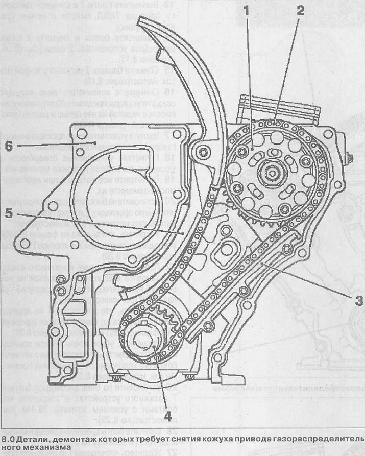
Attention! Dismantling the timing case is necessary when performing the following work:
  • removal and installation of sprocket 1 of the fuel injection pump drive,
  • removing and installing timing chain 2,
  • removal and installation of the 3rd timing chain damper,
  • removal and installation of the 4th timing gear drive sprocket from the crankshaft,
  • removal and installation of shoe 5 of the timing chain tensioner,
  • removal and installation of the casing 6 of the timing drive,
  • removing and installing the oil pump (see illustration 8.0). The oil pump is not visible in the illustration.
removing and installing the oil pump (see illustration 8.0). The oil pump is not visible in the…


Removal


1. Remove the engine (see the relevant chapter).

2. Remove the oil pan (see the relevant chapter).

3. Remove the cylinder head (see the relevant chapter).

4. Disconnect the wires from the generator.

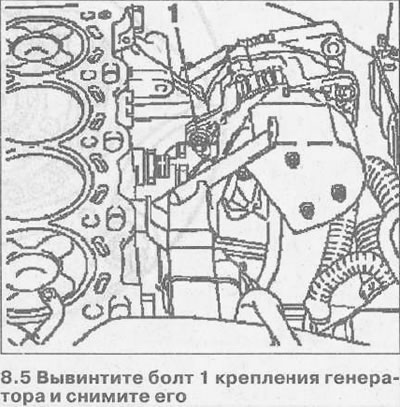
5. Unscrew the generator mounting bolt 1 and remove it (see illustration).
5. Unscrew the generator mounting bolt 1 and remove it (see illustration).


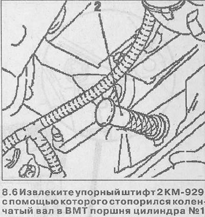
6. Remove the stop pin 2 KM-929, which was used to lock the crankshaft at TDC of the piston of cylinder No.1 (see illustration).


6. Remove the stop pin 2 KM-929, which was used to lock the crankshaft at TDC of the piston of…


7. Loosen bolt 1 securing the torsional vibration damper, holding the crankshaft from turning with device 2 KM-977-2 (see illustration). There is no need to completely unscrew the vibration damper bolt.
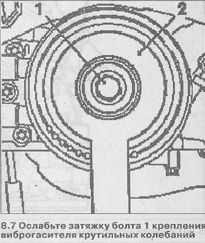
7. Loosen bolt 1 securing the torsional vibration damper, holding the crankshaft from turning with…


8. Lock the crankshaft with the stop pin 3 KM-929, inserting it into the hole of the shaft position sensor (see illustration).
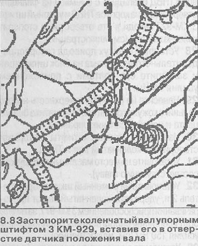
8. Lock the crankshaft with the stop pin 3 KM-929, inserting it into the hole of the shaft position…


In this position of the crankshaft, reference marks 4 should be positioned opposite each other (see illustration 8.8a).
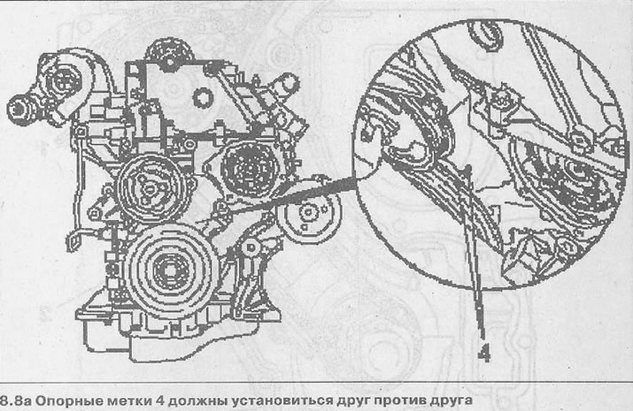


In this position of the crankshaft, reference marks 4 should be positioned opposite each other (see…


9. Remove the vibration damper from the accessory drive pulley.

10. Remove the timing chain tensioner 1
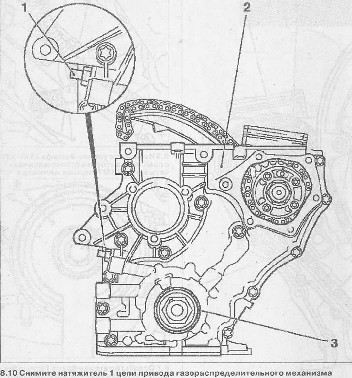
10. Remove the timing chain tensioner 1


11. Unscrew the bolts securing the casing 2 of the timing drive (see illustration 8.10).

Attention! Mark the mounting position of the bolts for their subsequent installation. The bolts have different lengths.


12. Remove oil seal 3 from the timing gear housing and make sure that the sealing surfaces are not damaged (see illustration 8.10).

13. Unscrew bolts 1 and remove the fuel injection pump drive sprocket together with the chain (see illustration).
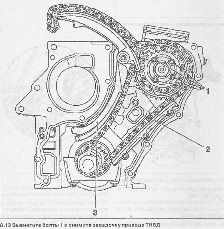
13. Unscrew bolts 1 and remove the fuel injection pump drive sprocket together with the chain (see…


14. Unscrew the bolts and remove the chain guide 2 from the cylinder block (see illustration 8.13).


15. Remove shoe 3 of the tensioner (see illustration 8.13).

16. Remove the timing drive sprocket from the crankshaft together with the chain attached to it and the previously removed fuel injection pump drive sprocket.

17. Remove the timing case sealing gasket.

18. Clean the sealing surfaces and remove any remaining old sealant.

19. Inspect all parts and replace them if necessary.

20. Install a new sealing gasket 1 of the timing case onto the cylinder block (see illustration).
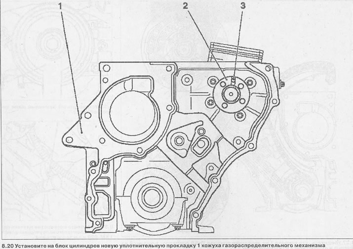
20. Install a new sealing gasket 1 of the timing case onto the cylinder block (see illustration).


21. Make sure that the recess on the flange 2 of the high-pressure fuel pump matches the hole 3 on the high-pressure fuel pump body (see illustration 8.20).

22. Check the condition of the spring ring and install sprocket 6 with chain 5 put on it on the crankshaft, and sprocket 3 on the high-pressure fuel pump shaft (see illustration).
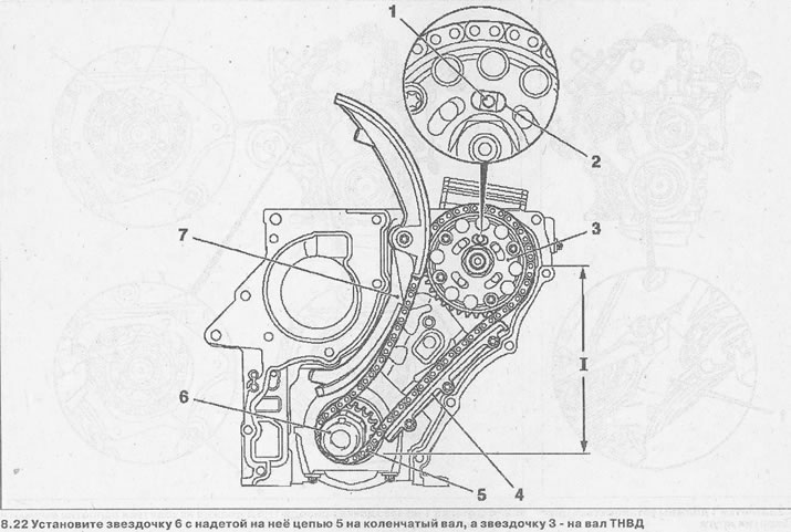
22. Check the condition of the spring ring and install sprocket 6 with chain 5 put on it on the…


23. Make sure that hole 1 on the fuel injection pump body is in the center of the recess (slot) 2 on the fuel injection pump flange (see illustration 8.22).


24. Install the 4th timing chain damper and tighten its mounting bolts to 8 Nm (see illustration 8.22).

25. Install shoe 7 of the tensioner on the cylinder block and secure it with bolts with a tightening force of 20 Nm (see illustration 8.22).

26. Screw in the fuel pump drive sprocket mounting bolts and tighten them by hand.

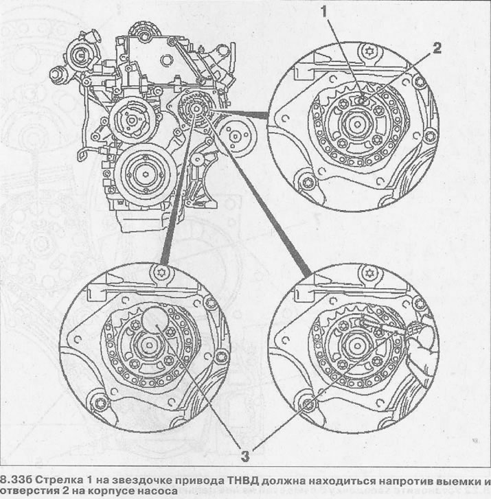
27. Make sure that the arrow 1 on the fuel injection pump drive sprocket coincides with the recess on the flange and the hole 2 on the fuel injection pump body and the thrust pin 3 KM-927 enters this hole and locks the crankshaft (see illustration).
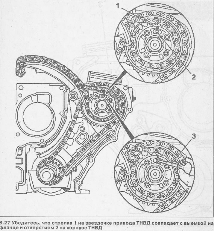
27. Make sure that the arrow 1 on the fuel injection pump drive sprocket coincides with the recess…


28. Install the timing gear housing onto the cylinder block and secure it with bolts applying a force of 20 Nm.

29. Apply a thin layer of white sealant to the working surface of the new casing seal and pack the seal with a mandrel.

30. Remove the stop pins that were used to lock the crankshaft and fuel injection pump.

31. Install the oil pan (see the relevant chapter).

32. Install vibration damper 2 on the belt pulley and, holding the crankshaft from turning with device 3 KM-977, tighten the vibration damper mounting bolt with a force of 150 Nm (see illustration).
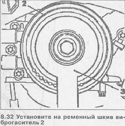


32. Install vibration damper 2 on the belt pulley and, holding the crankshaft from turning with…


33. Install the stop pin 1 KM-929 into the hole of the crankshaft position sensor and lock the shaft (see illustration). In this position of the crankshaft, the timing marks 1 should be positioned opposite each other, and the arrow 1 on the fuel injection pump drive sprocket should be positioned opposite the recess and hole 2 on the pump body (see illustrations 8.33a 8.33b).
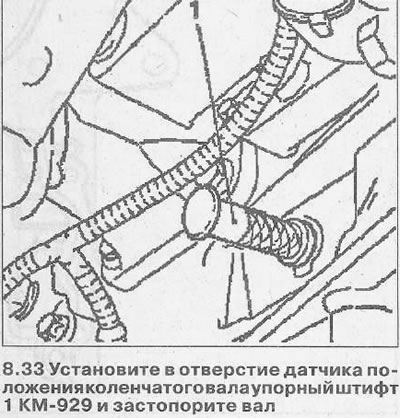
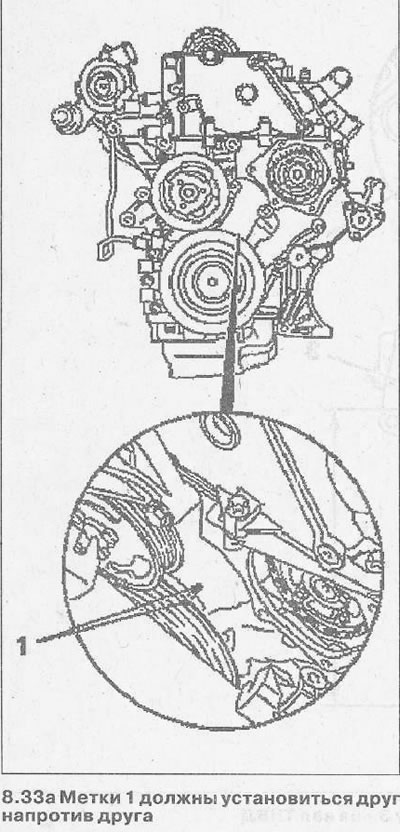
33. Install the stop pin 1 KM-929 into the hole of the crankshaft position sensor and lock the…


33. Install the stop pin 1 KM-929 into the hole of the crankshaft position sensor and lock the…


33. Install the stop pin 1 KM-929 into the hole of the crankshaft position sensor and lock the…


34. Lock the fuel injection pump by inserting the stop pin 3 KM-927 into hole 2 (see illustration 8.336).


35. Install the timing chain tensioner 5 in place and screw on its housing 3, replacing it with a new sealing ring 4 (see illustration).
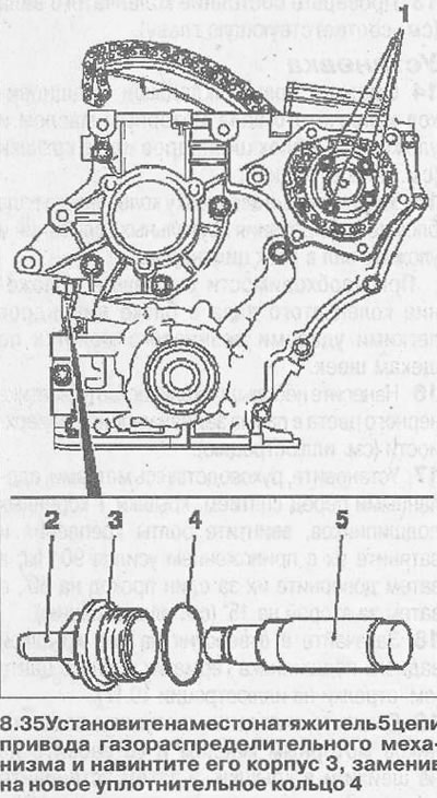
35. Install the timing chain tensioner 5 in place and screw on its housing 3, replacing it with a…


Subsequent installation of the dismantled parts is carried out in the reverse order of removal.


This article is available at russian, bulgarian, belarusian, ukrainian, serbian, croatian, romanian, polish, slovak, hungarian
Checking the article: Shapovalov Yaroslav

Share information:

Previous articles
Opel Omega B2: Diesel engines 2.0 l
Next articles

Vacuum pump — removal and installation
Camshaft — Removal and Installation
Cylinder head — overhaul
Cylinder head — removal and installation
TDC of piston of cylinder No. 1 — installation
Cylinder Head Cover — Removal and Installation
Oil pump — removal and installation
Crankshaft — removal and installation
Crankshaft — checks
Connecting rod and piston group — removal and installation
Flywheel — removal and installation
Rear Crankshaft Oil Seal — Removal and Installation


See similar ones from other Opel car manuals:
▶ Removal, condition check and installation of the camshaft… Opel Astra G (1998-2004)
▶ Removal and installation timing gear wheels Opel Corsa B (1993-2000)
▶ Gear Shift Lever Housing Assembly — Removal and Installation Opel Vectra A (1988-1995, petrol)
▶ Gear shift lever housing Opel Vivaro A (2001-2014)
▶ Checking the timing belt of the gas distribution mechanism Opel Insignia A (2008-2017)
Link to this page in different formats

Visitor comments


No comments yet


How much will 29 + 17 =


Omega B2 (1999-2003) 
  • General information
  • User manual
  • Maintenance
  • Troubleshooting
  • Power unit
  • Petrol 4-cylinder
  • Petrol 6-cylinder
  • Engine overhaul
  • Diesel engines 2.0 l
  • Diesel engines 2.5 l
  • Cooling and heating
  • Injection system (gasoline)
  • Fuel system (diesel)
  • Fuel system
  • Exhaust system
  • Ignition system
  • Transmission
  • Clutch
  • Mechanical gearbox
  • Automatic gearbox
  • Main gear and shafts
  • Chassis
  • Brake system
  • Car suspension
  • Steering
  • Body
  • Body elements
  • Electrical equipment
  • Equipment and devices
  • Electrical circuits
Omega B (1993-1999) 
  • General information
  • User manual
  • Tips for the car owner
  • Maintenance (gasoline)
  • Maintenance (diesel)
  • Power unit
  • Petrol engine SOHC 2.0 l
  • Petrol engine DOHC 2.0 l
  • Petrol engines 2.5 and 3.0 l
  • Repair of gasoline engines
  • Diesel engine 2.0 l
  • Diesel engine repair 2.0 l
  • Diesel engine 2.5 l
  • Cooling and heating
  • Power system (petrol)
  • Emission reduction
  • Fuel system (diesel 2.0 l)
  • Fuel system (diesel 2.5 l)
  • Launch system
  • Ignition system
  • Transmission
  • Clutch
  • Mechanical gearbox
  • Automatic gearbox
  • Drive shafts
  • Chassis
  • Brake system
  • Wheel suspension
  • Steering
  • Body
  • Exterior
  • Interior
  • Doors and windows
  • Electrical equipment
  • Equipment and devices
  • Wiring diagrams (early)
  • Wiring diagrams (late)
Omega A (1986-1993) 
  • General information
  • User manual
  • Maintenance
  • Changes and additions
  • Troubleshooting
  • Power unit
  • Gasoline engines
  • Diesel engines
  • Cooling system
  • Fuel system (gasoline)
  • Fuel system (diesel)
  • Ignition system
  • Transmission
  • Clutch
  • Mechanical gearbox
  • Automatic gearbox
  • Cardan shaft
  • Drive shafts
  • Chassis
  • Brake system
  • Car suspension
  • Steering
  • Body
  • Exterior
  • Interior
  • Electrical equipment
  • Power devices
  • Lighting and appliances
  • Electrical circuits
OpelBook.ru © 2017–2026 · Mobile version · · Sitemap: EN BG BY UA RS HR RO PL SK HU · Feedback · Site search
Astra F, petrol · Astra G, petrol · Astra G · Astra H · Astra J, petrol · Corsa B · Corsa C, petrol · Corsa C · Insignia A · Kadett D · Kadett E · Omega A · Omega B · Omega B2 · Vectra A, petrol · Vectra A · Vectra B, petrol · Vectra B · Vectra C · Zafira A, petrol · Frontera A, petrol · Frontera B · Ascona C · Vivaro A ·
We want your visit to be comfortable 🤝! We use cookies 🍪 to make that happen.