
2. Remove the vacuum pump (see relevant chapter).
3. Cars with air conditioning. Disconnect the air conditioning compressor and secure it, without disconnecting the hoses, to the body.
4. Remove the accessory drive belt tensioner (see relevant chapter).
5. Disconnect the charge air hose from the intercooler and lower intake manifold.
6. Disconnect the wire terminals from the battery «masses» (-) and positive potential and remove the battery.
7. Unscrew the bolts securing the protective cover 1 of the timing gear drive and carefully detach the cover with a spatula 2 (see illustration).
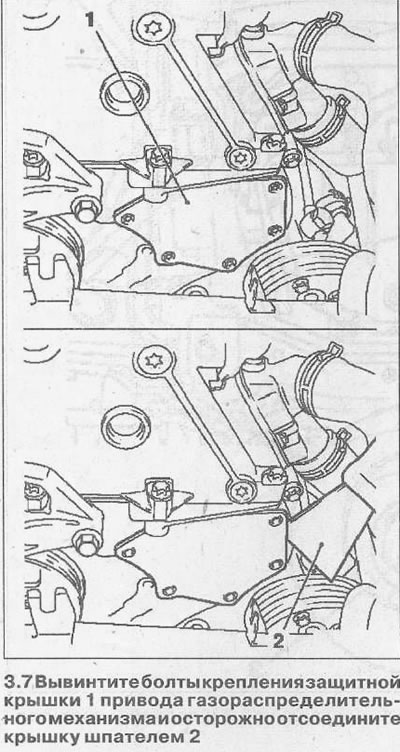
Attention! The protective cover of the timing gear drive should be disconnected carefully, avoiding its deformation. Otherwise, it may lead to its non-tightness.
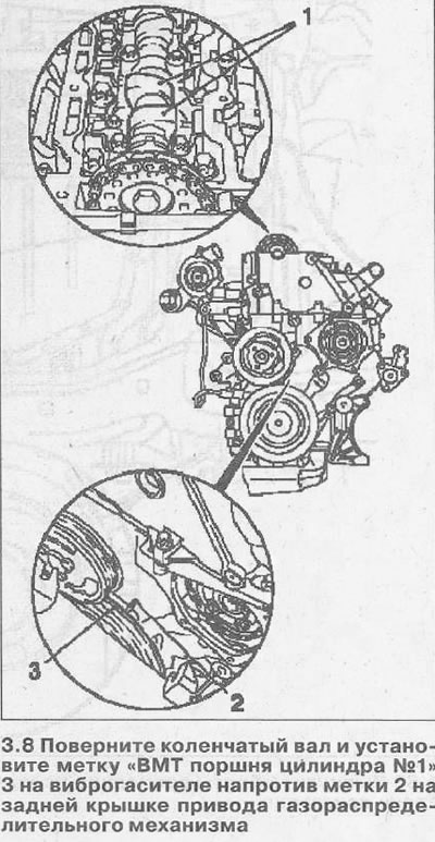
8. Turn the crankshaft in the direction of engine rotation at the vibration damper mounting bolt on the belt pulley so that the mark «TDC of the piston of the cylinder No. 1» 3 on the vibration damper was installed opposite the mark 2 on the rear cover of the gas distribution mechanism drive (see illustration). In this piston position, the lobes 1 of the camshaft point upwards.
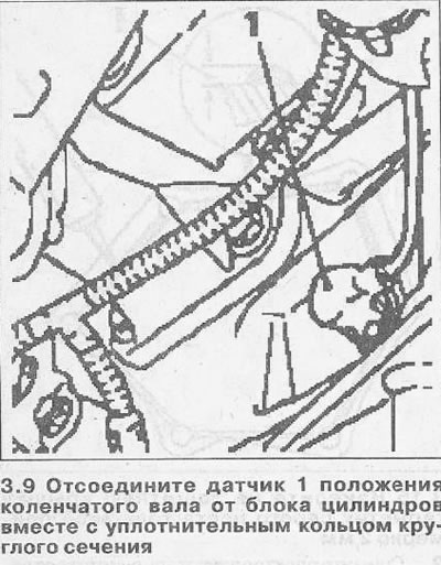
9. Disconnect the crankshaft position sensor 1 from the cylinder block together with the O-ring (see illustration).
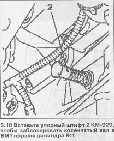
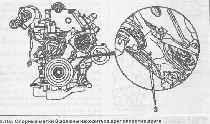
10. Insert thrust pin 2 KM-929 into the hole of the crankshaft position sensor to block the crankshaft at TDC of the piston of cylinder No. 1 (see illustration). If necessary, carefully turn the crankshaft in the direction of engine rotation until the thrust pin is seated in the appropriate hole. After fixing the crankshaft, reference marks 3 must be opposite each other (see illustration 3.10a).
11. Make sure that arrow 1 on the injection pump sprocket matches the slot on the injection pump flange and hole 2 (see illustration).
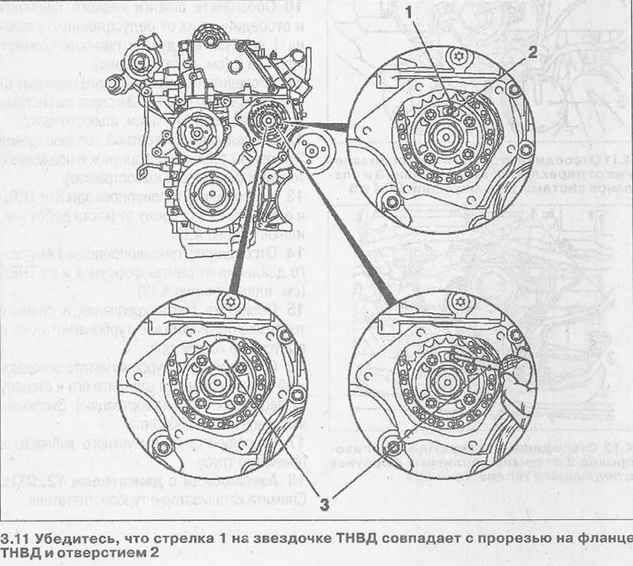
12. Fix the high pressure fuel pump in this position by inserting the thrust pin3 KM-927 into the hole 2 (see illustration 3.11).
Attention! If the thrust pin does not go into the hole, then repeat the installation of the piston of cylinder No. 1 at TDC.
13. Install tool 3 KM-932 on the cylinder head to fix the camshaft. Pin 2 must then go into hole 1 on the camshaft (see illustration).
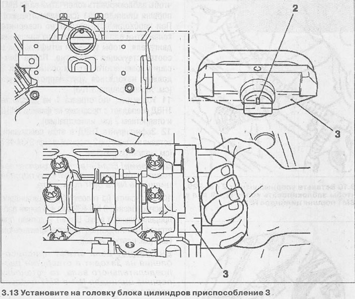
Attention! If the tool pin does not fit into the camshaft hole, then the installation of the piston of cylinder No. 1 at TDC should be repeated.
14. Remove the thrust pins, clean the sealing surfaces of the protective cover and the timing gear and wipe them with a clean, lint-free cloth.
15. Apply a gray sealant about 2 mm thick to the protective cover, install the cover and fasten it with bolts with a tightening torque of 6 Nm (see illustration).
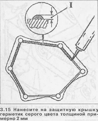
Attention! After applying the sealant to the protective cover, it should be replaced no later than 10 minutes later.
16. Reinstall the crankshaft position sensor, replacing its old O-ring with a new one. The tightening torque of the sensor is 8 Nm.
17. Connect the boost air hose to the intercooler and bottom of the intake manifold.
18. Replace the battery and connect the power wires.
19. Install the ribbed belt tensioner and A/C compressor, if equipped.
20. Install the vacuum pump and cylinder head cover.
Visitor comments