
Note: When installing, use new main bearing cap bolts.
Removing
1. After removing the engine, proceed as follows.
2. Remove the cylinder head as described in Chapter 20.
3. Remove the sump, oil pump pickup tube and sump deflector (where applicable), as described in Chapter 29.
4. Remove the oil pump as described in Chapter 30.
5. Remove flywheel or drive plate (depending on the model), as described in Chapters 25 and 26.
6. Remove pistons and connecting rods as described in Chapter 32.
7. Turn the engine block upside down.
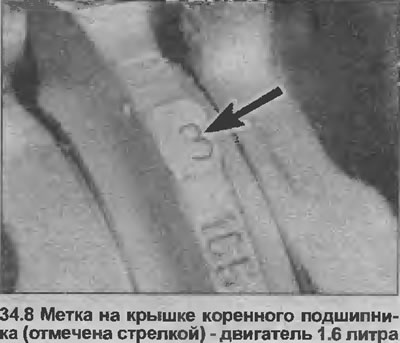
8. The main bearing caps are numbered 1 to 4: #1 is closest to the toothed drive belt. rear (flywheel) cover is not marked. To ensure the caps are properly oriented, note that the numbers are read from the coolant pump side when the engine is upside down (see illustration).
9. Turn off and remove bolts of a cover of the radical bearing, remove covers. If the earbuds are to be reused, tape them to the appropriate lids.
10. Note that the center bearing shell has thrust flanges that define the end clearance of the crankshaft.
11. Lift the crankshaft out of the crankcase (together with the ignition timing sensor wheel, if equipped).
12. Remove the top bushings, mark their position if they are to be reused.
13. The crankshaft, bearings, and sensor wheel can be examined for signs of wear and damage as described in Chapter 35, and the cylinder block and channels can be examined as described in Chapter 36.
Installation
14. Check that the crankcase and crankshaft are absolutely clean, that all lubrication grooves are not clogged; if possible, blow out the oil holes with compressed air and fill them with clean engine oil.
15. If the crankshaft is being replaced, move the ignition timing sensor wheel from the old crankshaft to the new one.
16. Wipe the bearing surfaces of the liners in the crankcase and covers, then install the upper liners in their places.
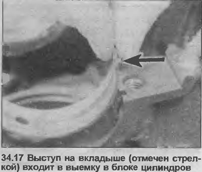
17. Please note that the tab at the end of each bushing must fit into a recess in the crankcase or cover (see illustration).
18. If new bearings are installed, wipe off the protective grease from them.
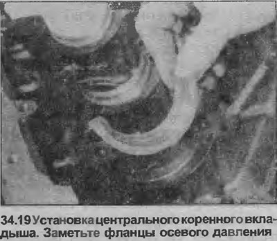
19. Note that the center bearing shells have thrust flanges that determine the crankshaft end clearance (see illustration). Note also that crankcase-mounted liners have lubrication holes, while caps only have a center liner with an oil hole.
20. After installing the liners in the crankcase and covers, lubricate them with clean engine oil.
21. Fill the sealing lips of the new crankshaft rear oil seal with grease, install it on the end of the crankshaft.
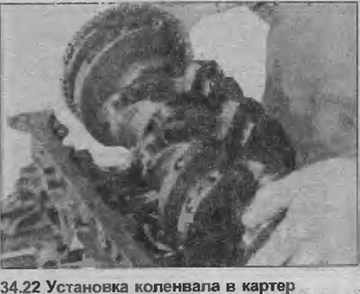
22. Gently lower the crankshaft into place in the crankcase (see illustration).
23. If necessary, seat the crankshaft by hitting the balance bars with a rubber mallet.
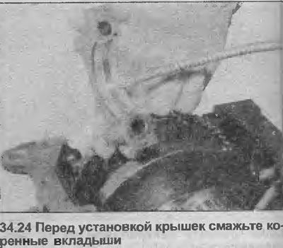
24. Lubricate the main journals and bearings (see illustration), then install the #2, #3, and #4 main bearing caps, hand-tighten the new bolts as far as possible.
25. Fill the rear grooves of the rear main bearing cap with special compound (Opel #90485251 or equivalent). Coat the bottom surfaces of the bearing cap with sealant (Opel #15 04 200 or equivalent). Install the bearing cover, tighten the new bolts by hand as far as possible.
26. Install the No. 1 propeller bearing front cover, hand-tighten the new bolts as far as possible.
27. Starting at the center bearing cap and outwards, tighten the cap bolts in two steps to the specified torque specifications; that is, torque all bolts to Stage 1, then torque all bolts to Stage 2 and Stage 3.
28. When all bolts are fully tightened, apply further special compound into the side grooves of the rear main bearing cap until they are completely filled.
29. Now rotate the crankshaft and check that it rotates freely, with no signs of slowing down or jamming.
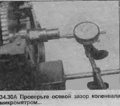
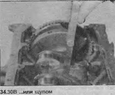
30. Check that the axial clearance of the crankshaft is within the limits specified in Specifications; use a micrometer for this or insert a feeler gauge between the center bearing thrust flange and the machined surface of the crankshaft (see illustrations). Before measuring, check that the crankshaft is completely moved to one end of the crankcase, creating the largest gap. Incorrect lateral play will most likely be due to wear on the crankshaft or after improper regrinding, provided that the correct size bearings have been installed.
31. Install previously removed components, guided by the relevant Chapters of this Section.
Visitor comments