
Note: The engine must be cold when removing the cylinder head. When installing, use new cylinder head bolts, a new cylinder head gasket and a new toothed drive belt. Tightening torques (as shown in Section 2A) only apply to the latest bolts. Bolts of early types are tightened with a different force. Please consult with your supplier.
Removing
1. Disconnect the negative cable from the battery.
2. Drain the cooling system as described in Section 3.
3. Remove the front of the exhaust system as described in Section 4C.
4. The cylinder head can be removed with the intake manifold, or the intake manifold can be separated from the cylinder head before removal, as described in Section 4B. If no work is to be done on the intake manifold, it can be unscrewed from the cylinder head and moved to the side, thus it will not be necessary to disconnect the corresponding hoses, pipes and wiring.
5. If the cylinder head is to be removed with the intake manifold, disconnect all relevant hoses, pipes and electrical wiring from the manifold and related components, following Section 4B; unscrew the mounting bracket from the manifold. Loosen the alternator fasteners as described in Section 5, then unscrew the alternator upper mount from the intake manifold.
6. If the intake manifold must be left in the engine compartment, proceed as follows, otherwise go to step 17.
7. Disconnect the wiring from the air flow meter and the breather hose from the heater block on the throttle body. Disconnect the air cleaner sleeve and remove the airflow meter/heater assembly from the throttle body. See Section 4B if it is needed.
8. Disconnect the end of the cable from the throttle lever, then unscrew the cable bracket and remove it from the intake manifold.
9. Unscrew the two fixing nuts of the ground loop from the fuel line (one at each end), and disconnect the three ground loops.
10. Disconnect wiring from throttle position switch.
11. Pull the casing off the wiring harness, disconnect the electrical wiring from the fuel injectors, squeezing the mounting brackets. Move the wiring harness cover to the side.
12. Disconnect the two breather hoses on the back of the camshaft cover.
13. Loosen the alternator mountings as described in Section 5, then unscrew the upper alternator mounting from the intake manifold.
14. Unscrew the bracket from the manifold.
15. Make a final check that there are no disconnected hoses, pipes and wires, then unscrew the fixing nuts and lift the intake manifold from the cylinder head. Make sure that the collector is securely fastened, take care not to deform the hoses, pipes, wires, etc. that are still connected.
16. Remove the manifold gasket from the cylinder head
17. Remove the toothed drive belt, camshaft sprockets tensioner and intermediate pulleys as described in Chapter 4.
18. Turn off the top and average racks for screws of fastening of an external cover of a driving belt. Note that the top strut just unscrews from the cylinder head, while the middle strut is attached with a bolt.
19. Turn off two top bolts of fastening of a back cover of a gear drive belt from a head of the block of cylinders
20. Remove the breaker-distributor cover and high voltage wires as described in Section 5.
21. Disconnect the distributor wiring.
22. Disconnect the coolant hose at the left end of the cylinder head
23. Remove the bolt securing the crankcase breather pipe bracket to the end of the cylinder head.
24. Disconnect the upper radiator hose from the thermostat housing, disconnect the electrical wiring from the temperature gauge sensor and the coolant temperature sensor (both are located in the thermostat housing).
25. Make a final check to ensure that all relevant hoses, pipes and wires have been disconnected.
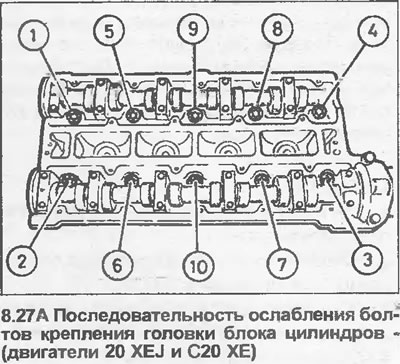
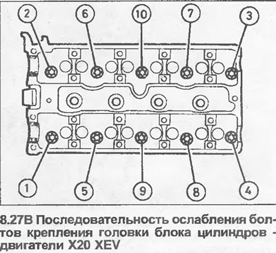
26. On the X20 XEV model, remove the camshaft as described in Chapter 7.
27. End socket in the order shown (see illustrations), loosen all cylinder head bolts a quarter of a turn, then loosen all bolts a half turn, and finally completely loosen and remove the bolts. Remove washers. Note that the bolt loosening sequence is different on X20 XEV and DOHC engines.
28. Lift the head off the cylinder block. If necessary, gently hit the head with a mallet to loosen it. Please note that the cylinder head is located on the pins.
29. Remove and discard the cylinder head gasket.
30. Clean the mating surfaces of the head and cylinder block. Do not damage the working surface of the head. Cover cooling ducts and other openings with adhesive tape or cloth to prevent dirt and deposits from entering. Remove all oil from the bolt holes, if oil is accidentally left in the holes, the hydraulic pressure may crack the block when screwing in the bolts.
31. If required, the cylinder head can be disassembled and inspected as described in Chapter 10.
Installation
32. Installation begins by placing a new gasket on the block so that the word "OBEN" or "TOR" should be facing up and located at the end of the motor with the toothed drive belt.
33. After carefully cleaning the mating surfaces, position the head on the block so that the pins fit into their respective holes,
34. Temporarily install the crankshaft pulley and camshaft sprockets, before removing the toothed drive belt, check that the alignment marks remain in place (see chapter 4).
35. Install new cylinder head bolts with washers, screw them in by hand as far as possible.
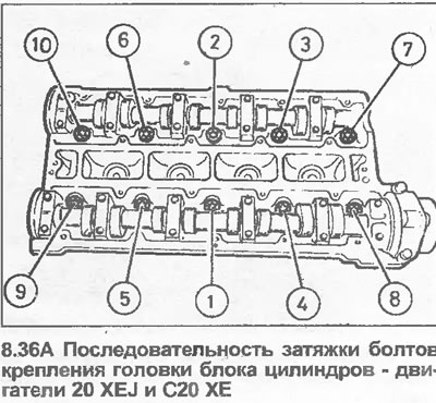
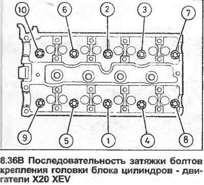
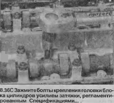
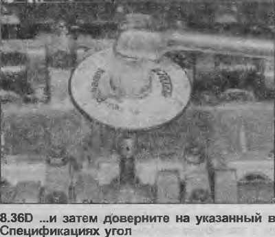
36. Tighten the bolts in the order shown (see illustrations). Note that the tightening sequence on X20 XEV engines is different from other DOHC engines. Tighten the bolts in four stages data per Specifications (see Section 2A, for 2.0 liters) - i.e. tighten all bolts with Stage 1 torque, then tighten all bolts with Stage 2 torque and so on (see illustrations).
37. Further installation is carried out in the figurative order, paying attention to the following.
38. Install the timing belt tensioner and idler pulleys, camshaft sprockets and new timing belt as described in Chapter 4. Tighten the toothed drive belt as described in Chapters 4 and 5.
39. Where necessary, install the intake manifold to the cylinder head as described in Section 4B, using a new gasket.
40. Install the front end of the exhaust system as described in Section 4C, using a new gasket.
41. Install the alternator top mount to the intake manifold (where applicable), then adjust the alternator drive belt tension as described in Section 5.
42. Fill the cooling system (Section 3).
43. Finally, make sure that all relevant hoses, pipes, wires, etc., have been reconnected.
44. After starting the engine, check for leaks.
45 Once the engine has warmed up to normal operating temperature, check and, if necessary, adjust the quality of the mixture (if it is possible), as described in Section 4B.
Visitor comments