


Note: The timing belt must be replaced during installation. A two-pronged puller may be required to remove the crankshaft sprocket.
Removal
1. Disconnect the negative cable from the battery.
2. Disconnect the air cleaner tube from the air flow meter, then remove the cover and filter element from the air cleaner. If necessary, the entire air cleaner assembly can be removed for better access as described in Section 4B.
3. Remove the power steering pump drive belt as described in Section 10.
4. Remove the alternator drive belt as described in Section 5.
5. Unscrew the three fastening screws, remove the outer cover of the toothed drive belt. Remove the rubber sealing rings from the screw holes in the cover if they are loose.
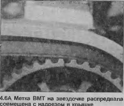
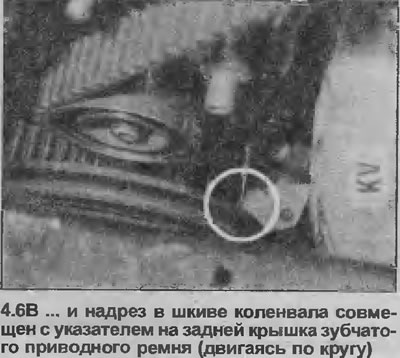
6. Rotate the crankshaft until the timing marks on the camshaft sprockets align with the notch in the camshaft cover. The notch in the crankshaft pulley should also align with the pointer on the rear timing belt cover (see illustrations).
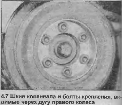
7. Unscrew the six mounting bolts and remove the crankshaft pulley (see illustration), If necessary, hold the crankshaft from turning with a socket on the bolt and the crankshaft sprocket. If the engine is not removed from the car, the crankshaft can be locked by engaging 1st gear and pressing the brake pedal. You can also use a large screwdriver, inserting it into the teeth of the flywheel ring gear. Before removing the pulley, make sure that the timing marks have not shifted.
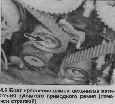
8. Loosen the mounting bolt, release the toothed belt tensioner pulley, then pull the belt off the sprockets and pulleys (see illustration).
9. If required, the sprockets, tensioner, idler pulleys and rear timing belt cover can be removed as follows, otherwise proceed to step 27.
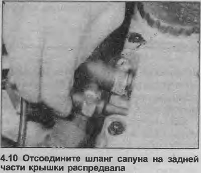
10. To remove the camshaft sprockets, first disconnect the breather hoses from the camshaft cover (see illustration).
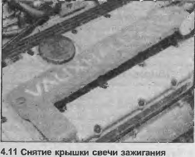
11. Remove the two mounting bolts and remove the spark plug cover (see illustration), then disconnect the high-tension wires from the spark plugs, unfasten them from the end of the camshaft cover. If necessary, mark the position of the wires so as not to mix them up during installation.
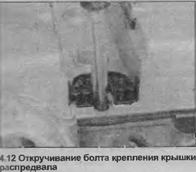
12. Unscrew the twenty mounting bolts and remove the camshaft cover (see illustration).
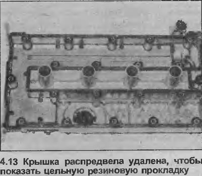
13. Remove the solid rubber gasket (see illustration).
14. Holding the camshaft from turning by the cam contour, unscrew the camshaft sprocket bolt (see illustration).
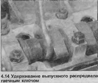
15. Remove the sprocket from the end of the camshaft, then repeat the procedure with the remaining camshaft sprocket.
16. Remove the crankshaft sprocket This will require preventing the crankshaft from rotating by attaching a metal rod to the sprocket with two crankshaft pulley bolts, or by pinching the flywheel ring gear. You will need a socket to loosen the sprocket bolt - keep in mind that the bolt is very tightly clamped. If necessary, use a two-pronged puller to remove the sprocket. Remove the thrust washers from the end of the crankshaft and from under the bolt head.
17. To remove the belt tensioner pulley, simply unscrew the mounting bolt in the center of the pulley, then remove the pulley along with the mounting plate (see illustration). Remove the spacer sleeve from the pulley bolt.
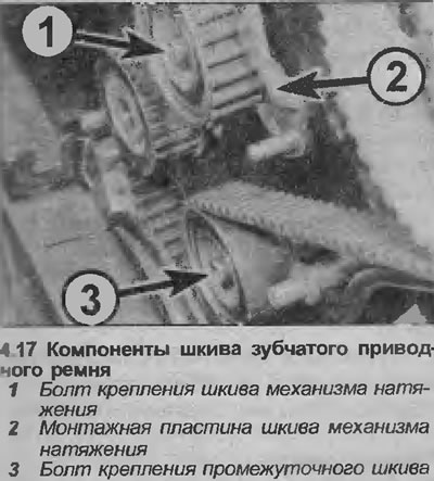
18. To remove the belt tensioner pulley, unscrew the mounting bolt in the center of the pulley, then remove the pulley itself and the spacer sleeve from the pulley bolt
19. Now you can remove the rear toothed belt cover by unscrewing the top and middle posts for the outer cover mounting screws.
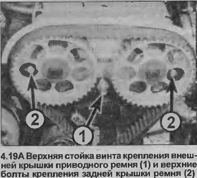
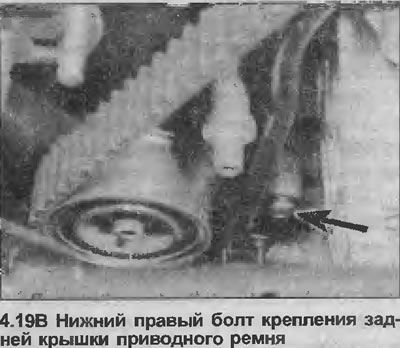
Note that the top strut simply unscrews from the cylinder head, while the middle one is attached with a bolt. Remove the two upper and one lower right bolt securing the rear belt cover, and remove the rear cover (see illustrations).
Installation
20. Installation of the rear cover of the toothed drive belt is carried out in the reverse order of removal.
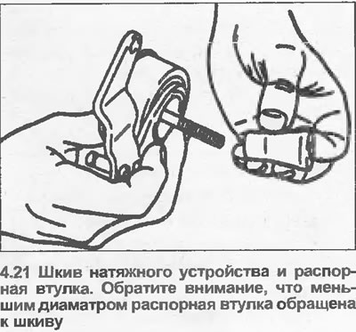
21. Install the tensioner pulleys, the spacer bushings are installed with a smaller diameter towards the pulley (see illustration). Do not fully tighten the tensioner pulley mounting bolts yet.
22. Install the thrust washer on the end of the crankshaft, then install the sprocket. Apply a little grease to the threads of the mounting bolt, tighten it in two stages with the tightening force specified Specifications. Make sure the thrust washer is in place under the bolt head, hold the crankshaft from turning as you did when removing it.
23. Install the camshaft sprockets. Make sure that the dowel pins on the ends of the camshafts fit into the holes in the sprockets, with the sprockets with the timing marks facing forward. Then tighten the mounting bolts in two stages to the specified tightening torque Specifications. Hold the camshafts from turning as you did when removing them.
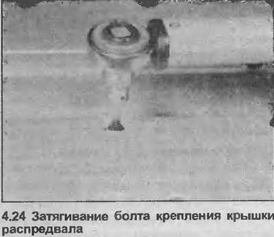
24. Check the condition of the rubber gasket of the camshaft cover, replace if necessary. Then install the camshaft cover and tighten the mounting bolts (see illustration).
25. Install the high tension wires to the spark plugs, then secure the wires with the clamps at the end of the camshaft cover. Install the spark plug cover, and tighten the mounting bolts.
26. Connect the breather hose to the camshaft cover.
27. Temporarily install the crankshaft pulley. Make sure the timing marks on the crankshaft pulley and camshaft sprockets are aligned as described in step 6. Then install the new timing belt onto the sprockets and pulleys, starting with the crankshaft sprocket.
28. Install the crankshaft pulley, tighten the mounting bolts with the specified tightening force Specifications. If necessary, hold the crankshaft from turning as you did when removing it.
29. Adjust the tension of the toothed drive belt as described starting from point 35.
30. Install the outer timing belt cover. Make sure the rubber sealing rings are in place in the screw holes, then tighten the mounting screws.
31. Install the alternator drive belt, adjust the drive belt tension as described in Section 5.
32. Install the power steering pump drive belt, adjust the drive belt tension as described in Section 10.
33. Install the air filter components according to the Section 4B, if necessary.
34. Connect the negative battery cable.
Adjustment
Note: Manufacturers recommend using the Opel special tool #KM-666 to adjust the timing belt tension. If this tool is not available, a rough adjustment can be made using the method described in this Chapter. However, it should be emphasized that after the adjustment, you should still contact your dealer as soon as possible to perform a proper tension adjustment using the special tool.
Approximate adjustment
35. The timing belt adjustment cannot be checked and the following adjustment procedure is only applicable to a newly installed belt (the engine must be cold).
36. With the timing belt cover removed and the tensioner pulley bolts loosened, check that the TDC marks on the camshaft sprockets and crankshaft pulley are aligned as described in step 6. If necessary, rotate the crankshaft to achieve alignment.
37. Press the tensioner pulley into the flint until the belt can be turned only 45°, applying moderate force with your thumb and forefinger on the longest section of the belt between the exhaust camshaft sprocket and the tensioner pulley.
38. Fix the tensioner pulley in this position, tighten the tensioner pulley bolt in two stages to the tightening torque specified in the Specifications.
39. Turn the crankshaft clockwise two full turns, the TDC mark on the crankshaft pulley should again align with the pointer on the rear cover of the toothed drive belt, and the TDC marks on the camshaft sprockets should align with the notches in the camshaft cover.
40. Then proceed as described in paragraphs 30-34 inclusive.
41. Then contact your Opel dealer as soon as possible to adjust the belt tension.
Adjustment with special tool Opel (KM-666)
42. Proceed as described in points 35 and 36.
43. Install the special tool KM-666 on the tensioner pulley mounting plate according to the manufacturer's instructions.
44. Counterclockwise from the TDC mark on the exhaust camshaft sprocket, count the seventh tooth (see illustration).
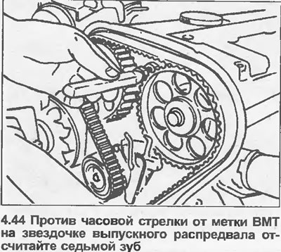
45. Turn the crankshaft clockwise until this tooth aligns with the TDC notch in the camshaft cover. The crankshaft must be turned evenly, without jerking, to prevent the toothed drive belt from jumping off the sprockets and pulleys.
46. In two stages, tighten the tensioner pulley bolt to the specified tightening force Specifications.
47. Remove the special tool.
48. Turn the crankshaft clockwise until the TDC marks on the camshaft sprockets align with the notches in the camshaft cover, check that the TDC mark on the crankshaft pulley aligns with the pointer on the rear toothed drive belt cover.
49. Proceed as described in paragraphs 30-34 inclusive.
Visitor comments