
Note: During 1989, some vehicles were produced with the brake pedal properly installed (approximately 15.0 above the clutch pedal instead of normally 4.0 mm below it). The correct pedal height can be achieved by adjusting the working length of the vacuum booster fork as described in paragraphs 15 and 16.
Removing
1. Disconnect the negative cable from the battery.
2. While working inside, remove the lower trim panel from the driver's footwell.
3. Disconnect the wiring connector from the brake light switch, then unscrew the switch counterclockwise and remove it from the bracket.
4. Pull the spring clip from the right end of the pivot pin that secures the booster fork to the pedal.
5. Using pliers, unfasten the end of the return spring from the pedal and remove the pivot pin that secures the booster fork to the pedal.
6. Remove the windshield fairing as described in Section 11, then remove the wiper motor and linkage as described in Section 12.
7. Remove the coolant expansion tank as described in Section 3.
8. Disconnect the vacuum tube from the brake booster.
9. Turn off two fixing nuts and accurately remove the main brake cylinder from racks on the amplifier. Slightly move the master cylinder forward, being careful not to deform the brake pipes.
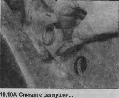
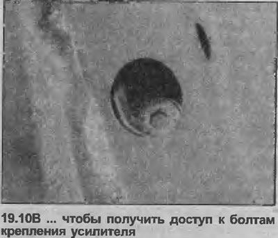
10. Remove the two plugs covering the amplifier mounting bolts (see illustrations).
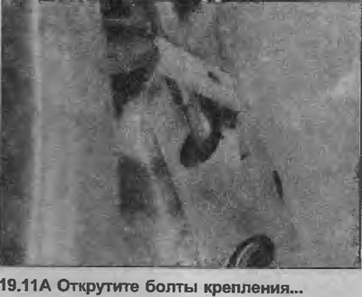
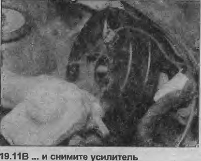
11. Unscrew the bolts securing the amplifier with a socket wrench and remove them, then remove the amplifier from the bulkhead (see illustrations).
12. If required, remove the mounting bracket from the amplifier by unscrewing the four mounting nuts. Please note that the bracket is seated on the amplifier with a sealant.
13. It is impossible to sort out the amplifier, if it is faulty, replace the unit.
Installation
14. Before installing the booster, make sure the working fork length is correct, as described below.
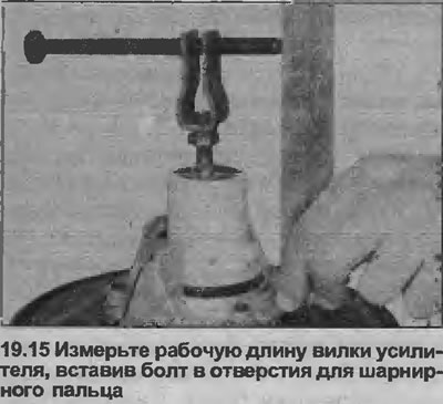
15. Measure the distance from the end of the booster housing to the center of the pivot pin hole in the yoke. Distance should be 144.0 mm To facilitate measurement, insert a bolt or rod of suitable diameter through the hinge pin holes and mark its center (see illustration).
16. If adjustment is needed, loosen the locknut and rotate the fork to the desired length, then tighten the locknut.
17. Where applicable, coat the contact surfaces of the amplifier and mounting bracket with sealant, then install the bracket on the amplifier and tighten the mounting nuts to the specified torque specifications.
18. Coat the threads of the amplifier mounting bolts with blocking compound, then install the amplifier on the bulkhead and tighten the bolts.
19. Establish plugs of bolts of fastening of the amplifier.
20. Install the main cylinder on the amplifier and tighten the fixing nuts with a tightening torque regulated specifications.
21. Connect the vacuum tube to the booster.
22. Install the coolant expansion tank as described in Section 3.
23. Install the wiper motor and linkage as described in Section 12 then install the windshield fairing.
24. Next, install in reverse order. Finally, check the operation of the amplifier as described in Chapter 18.
Visitor comments