
1. With the engine off, depress the brake pedal 4-5 times and keep the pedal depressed.
2. Start the engine. As the RPMs increase, you should feel a reduction in pedal pressure on your foot, indicating that there is a vacuum in the booster.
3. Let the engine run for 2 minutes and stop it.
4. Step on the brake pedal (ask an assistant) and put your ear as close to the vacuum booster as possible. When you press the pedal, you should hear "hiss", accompanying the process of vacuum formation. The sound disappears after 4-5 pedal presses.
Removing
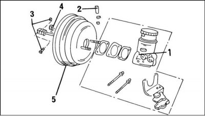
View of the vacuum brake booster
Explanations for positions are given in the text.
1. Removal of the vacuum amplifier is made according to an illustration Type of the vacuum amplifier of a brake.
In this case, the description refers to the model from the middle of 1995 release. On earlier models, the removal process is similar.
2. Disconnect the ground cable from the battery.
3. Remove the brake master cylinder (1), as described for the vehicle of the corresponding model year.
4. Loosen the clamp and remove the vacuum hose (2) from the pipe on the vacuum booster.
5. Disconnect the plug from the cabin side (3) from the brake pedal. To do this, remove the spring clip from the end of the pusher pin.
6. Loosen the four fixing nuts (4) amplifier (5) from the front wall of the engine compartment. The bottom nut can be unscrewed using a swivel head with an extension.
7. Remove the amplifier from the engine compartment by turning it accordingly.
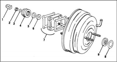
External parts of the vacuum booster
Only the parts shown in the illustration are subject to replacement during repair. Explanations for positions are given in the text.
1. Loosen the locknut (2) and fork (1).
2. Remove the clip (3).
3. Remove protective cover (4) valve body.
4. Remove shock absorber (5).
5. Remove filter (6), two seals and one spacer (7).
6. Remove the holder with a screwdriver (8) on the other side of the brake booster and press out the bar and seal (9).
Before installing any parts, check the fork, boot, shock absorber, filter and seal bar and replace if necessary.
Assembly
Assembly is carried out in accordance with the illustration External parts of the vacuum booster in the sequence shown. The fork fastening nut is tightened with a torque of 20 Nm.
Installation of the vacuum amplifier is carried out as described below. If the vacuum booster is replaced, it must be adjusted. In this case, it is necessary to distinguish between the old and new versions:
1. Install the vacuum booster and secure it with nuts. On a car up to the middle of 1995, tighten the nuts with a torque of 21 Nm.
2. When putting on the vacuum hose, pay attention to the direction of the arrow on the hose. The arrow should point towards the engine.
3. Other work is carried out in the reverse order of removal.
4. Finally, check the operation of the vacuum pump as described at the beginning of this section.
If the vacuum booster was replaced with a new one
If the vacuum booster of the new series has been replaced since the middle of 1995, the pusher cannot be adjusted by conventional means, since this requires a vacuum pump and gauge. Here we can only hope that the adjustment of the removed part corresponds to the adjustment of the new part.
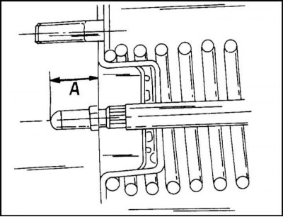
On an older car, the tappet can be measured and adjusted. The protruding part of the pusher is measured from the plane of the flange on the vacuum booster to the end of the pusher. In the illustration, this is the size "A". If this dimension is outside 18.0-18.2 mm, the pusher locknut is loosened and the pusher turns. The nut is tightened with a torque of 27 Nm.
Visitor comments